


– 11 –
SMMS Concealed Duct High Static Pressure Type
Installation Manual
SMMS Concealed Duct High Static Pressure Type
Installation Manual
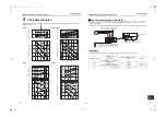
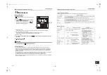
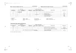
• Use the tightening torque levels as listed in the table
below.
• Tightening torque of flare pipe connections.
Pressure of R410A is higher than that of R22.
(Approx. 1.6 times) Therefore, using a torque
wrench, tighten the flare pipe connecting sections
which connect the indoor and outdoor units of the
specified tightening torque.
Incorrect connections may cause not only a gas leak,
but also a trouble of the refrigeration cycle.
CAUTION
Tightening with an excessive torque may crack the nut
depending on installation conditions.
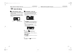
Airtight test / air purge, etc.
For air tightness test, adding refrigerant, refer to the
Installation Manual attached to the outdoor unit.
CAUTION
Do not supply power to the indoor unit until the airtight
test and vacuuming are completed. (If the indoor unit is
powered on, the pulse motor valve is fully closed, which
extends the time for vacuuming.)
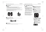
Open the valve fully
Open the valve of the outdoor unit fully.
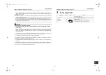
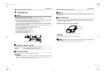
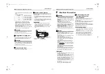
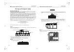
Heat insulation process
Apply heat insulation for the pipes separately at liquid
side and gas side.
• For the heat insulation to the pipes at gas side, use
the material with heat-resisting temperature 120 °C
or higher.
• To use the attached heat insulation pipe, apply the
heat insulation to the pipe connecting section of the
indoor unit securely without gap.
REQUIREMENT
• Apply the heat insulation to the pipe connecting
section of the indoor unit securely up to the root
without exposure of the pipe. (The pipe exposed to the
outside causes water leak.)
• Wrap heat insulator with its slits facing up (ceiling
side).
Outer dia. of connecting
pipe (mm)
Tightening torque (N•m)
6.4
14 to 18 (1.4 to 1.8 kgf•m)
9.5
33 to 42 (3.3 to 4.2 kgf•m)
12.7
50 to 62 (5.0 to 6.2 kgf•m)
15.9
63 to 77 (6.3 to 7.7 kgf•m)
Indoor unit
Union
Heat insulation pipe
(Accessory)
Banding band
(locally procured)
Heat insulator of
the pipe
Flare nut
8
Electrical Connection
WARNING
•
Use the specified wires for wiring connect the
terminals. Securely fix them to prevent external
forces applied to the terminals from affecting the
terminals.
Incomplete connection or fixation may cause a fire or
other trouble.
•
Connect earth wire. (grounding work)
Incomplete grounding cause an electric shock.
Do not connect earth wires to gas pipes, water pipes,
lightning conductor or telephone earth wires.
•
Appliance shall be installed in accordance with
national wiring regulations.
Capacity shortage of power circuit or incomplete
installation may cause an electric shock or a fire.
CAUTION
• If incorrect / incomplete wiring is carried out, it will
cause an electrical fire or smoke.
• Install an earth leakage breaker that is not tripped by
shock waves.
If an earth leakage breaker is not installed, an electric
shock may be caused.
• Use the cord clamps attached to the product.
• Do not damage or scratch the conductive core and
inner insulator of power and inter-connecting wires
when peeling them.
• Use the power cord and Inter-connecting wire of
specified thickness, type, and protective devices
required.
• Do not connect 220 V – 240 V power to the terminal
blocks (
,
,
,
) for control wiring. (Otherwise,
the system will fail.)
• Do not damage or scratch the conductive core and
inner insulator of power and inter-connecting wires
when peeling them.
• Perform the electric wiring so that it does not come to
contact with the high-temperature part of the pipe.
The coating may melt resulting in an accident.
REQUIREMENT
• For power supply wiring, strictly conform to the Local
Regulation in each country.
• For wiring of power supply of the outdoor units, follow
the Installation Manual of each outdoor unit.
• Perform the electric wiring so that it does not come to
contact with the high-temperature part of the pipe.The
coating may melt resulting in an accident.
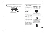
• After connecting wires to the terminal blocks, provide
a trap and fix wires with the cord clamp.
• Run the refrigerant piping line and control wiring line in
the same line.
• Do not turn on the power of the indoor unit until
vacuuming of the refrigerant pipes completes.
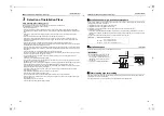
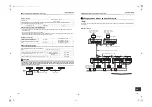
Power supply wire and
communication wires
specifications
Power supply wire and communication wires are
procured locally.
For the power supply specifications, follow to the table
below. If capacity is little, it is dangerous because
overheat or burnout may be caused.
For specifications of the power capacity of the outdoor
unit and the power supply wires, refer to the Installation
Manual attached to the outdoor unit.
Indoor unit power supply
• For the power supply of the indoor unit, prepare the
exclusive power supply separated from that of the
outdoor unit.
• Arrange the power supply, circuit breaker, and main
switch of the indoor unit connected to the same
outdoor unit so that they are commonly used.
• Power supply wire specification: Cable 3-core 2.5
mm²,
in conformity with Design 60245 IEC 57
.
U
1
U
2
A
B
21-EN
22-EN
+00EH99879501_01EN.book Page 11 Monday, March 14, 2011 10:06 PM