


– 26 –
Co
nfir
mati
on
of
ind
o
o
r u
n
it
setu
p
Prior
to
deliv
e
ry to
the cu
s
tome
r, che
c
k
the a
ddr
ess and
s
e
tup o
f the
in
door
un
it,
which h
a
s bee
n installed in t
h
is
tim
e
an
d fi
ll
the che
c
k sh
eet (
F
ollo
wing
table)
.
Da
ta of f
our
units can b
e
en
ter
ed in th
is che
c
k sh
eet. Copy t
h
is sh
eet accor
d
ing
to the
No
. of th
e indoo
r u
n
its. If th
e install
ed system is a
group con
tro
l s
yste
m
, use
this sheet
by ente
ring
each line system into e
a
ch inst
allation
man
ual atta
c
h
ed to
the o
ther indo
or
units.
REQUI
R
EMENT
This check
she
et i
s
r
equired fo
r maintenance
after
install
a
tion.
Fil
l this s
heet and
then pass this In
stallation Man
ual
to
the
cust
om
ers.
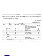
In
door
unit setup
che
ck sh
eet
Indoor uni
t
Indoor
unit
Indoor uni
t
Indoor uni
t
Room
name
Room name
R
oom na
me
Room
name
M
ode
l
M
odel
M
odel
M
odel
Check i
n
door unit addr
ess.
(F
or
chec
k m
e
thod, re
fer
to
AP
PL
ICABLE CONTR
O
LS
in
thi
s
m
anual.)
*In
c
ase of a si
n
gl
e sys
tem
, it i
s
unne
cessar
y
to enter the
indoor
ad
dress
. (COD
E NO.:
Line [1
2
],
Indoor
[13], Group [14], C
e
n
tr
a
l control [03])
Li
ne
Indoor
Group
Line
Indo
or
G
roup
Li
ne
Indoor
Group
Line
Indoor
Group
Cent
ral
control
address
Central
c
ont
rol
a
ddress
Ce
nt
ral
cont
rol
addres
s
C
entral
control
address
Vari
ous setup
Various
s
e
tup
Vari
ous set
up
V
a
riou
s
setup
Have you changed
high ceil
ing setup? If
no
t,
fi
ll
ch
eck mar
k
[×]
in [NO
CHANGE], and fill
check
m
a
rk
[×] in
[ITEM
] if change
d,
res
pecti
vely.
(For
c
heck method, refer t
o
APPLIC
ABLE CO
NTROLS
in t
h
is man
ual
.)
*
In
cas
e
of
replacement of
ju
mper blocks
on
indoor mi
c
rocompu
ter P.C.
bo
ard,
setup i
s
automa
ticall
y
chan
ged.
Ex
ter
nal stati
c
pre
ssure
(C
ODE NO.
[5d]
)
NO
CH
A
N
G
E
S
TANDARD
[0000]
S
T
ATIC 1
[0001]
S
T
ATIC 2
[0002]
S
T
ATIC 3
[0003]
S
T
ATIC 4
[0004]
S
T
ATIC 5
[0005]
S
T
ATIC 6
[0006]
Exte
rnal s
tatic pr
essur
e
(C
O
D
E NO
.
[5d])
NO
CHAN
G
E
STAND
ARD
[0
0
00]
STATIC 1
[00
01]
STATIC 2
[00
02]
STATIC 3
[00
03]
STATIC 4
[00
04]
STATIC 5
[00
05]
STATIC 6
[00
06]
Extern
al
static pres
sure
(C
O
D
E
N
O
.
[5
d])
NO CHANG
E
STANDAR
D
[0000]
STATIC 1
[0001]
STATIC 2
[0002]
STATIC 3
[0003]
STATIC 4
[0004]
STATIC 5
[0005]
STATIC 6
[0006]
Exter
nal stati
c
pr
essur
e
(CO
DE N
O.
[5d])
N
O
CH
ANGE
STAN
DARD
[0000
]
STATIC 1
[0001
]
STATIC 2
[0002
]
STATIC 3
[0003
]
STATIC 4
[0004
]
STATIC 5
[0005
]
STATIC 6
[0006
]
Have you changed
li
g
hting time
of
fil
ter si
gn? If
no
t,
fi
ll
ch
eck mar
k
[×]
in [NO
CHANGE], and fi
ll chec
k
m
a
rk
[×] in
[ITEM
] if
chang
ed, res
pecti
ve
ly
.
(For
c
heck method, refer t
o
APPLIC
ABLE CO
NTROLS
in t
h
is man
ual
.)
Fil
ter sign l
ighti
n
g
ti
m
e
(C
ODE NO.
[01]
)
NO
CH
A
N
G
E
N
O
NE
[0000]
150H
[0001]
2500H
[0002]
5000H
[0003]
10000H
[0004]
Filter
s
ign
lighting time
(C
O
D
E NO
.
[01])
NO
CHAN
G
E
NO
NE
[0
0
00]
150H
[00
01]
2500H
[00
02]
5000H
[00
03]
10000
H
[00
04]
Fi
lter
sign
light
ing t
ime
(C
O
D
E
N
O
.
[0
1])
NO CHANG
E
NONE
[0000]
15
0H
[0001]
25
00H
[0002]
50
00H
[0003]
10
000H
[0004]
Fil
ter
sign
lighti
n
g ti
m
e
(CO
DE N
O.
[01])
N
O
CH
ANGE
N
O
NE
[0000
]
150H
[0001
]
2500H
[0002
]
5000H
[0003
]
10000H
[0004
]
Have you changed
detected tem
p.
sh
ift value? If
n
o
t, fil
l c
heck
ma
rk
[×] in
[NO CHANGE
], and
fi
ll
chec
k m
a
rk
[×] in [ITE
M
] if
c
han
ged, re
specti
v
el
y
.
(For
c
heck method, refer t
o
APPLIC
ABLE CO
NTROLS
in t
h
is man
ual
.)
Det
ect
ed tem
p.
shif
t value setu
p
(C
ODE NO.
[06]
)
NO
CH
A
N
G
E
N
O
SH
IFT
[0000]
+1°C
[0001]
+2°C
[0002]
+3°C
[0003]
+4°C
[0004]
+5°C
[0005]
+6°C
[0006]
Det
e
ct
ed tem
p
. s
h
ift
v
a
lue s
e
tup
(C
O
D
E NO
.
[06])
NO
CHAN
G
E
NO SHIFT
[00
00]
+1°
C
[00
01]
+2°
C
[00
02]
+3°
C
[00
03]
+4°
C
[00
04]
+5°
C
[00
05]
+6°
C
[00
06]
Det
e
ct
ed
te
m
p
. shift
val
u
e
se
tup
(C
O
D
E
N
O
.
[0
6])
NO CHANG
E
NO SHIFT
[0000]
+1
°C
[0001]
+2
°C
[0002]
+3
°C
[0003]
+4
°C
[0004]
+5
°C
[0005]
+6
°C
[0006]
D
etected tem
p.
sh
ift value setup
(CO
DE N
O.
[06])
N
O
CH
ANGE
N
O
SHIFT
[0000
]
+1°C
[0001
]
+2°C
[0002
]
+3°C
[0003
]
+4°C
[0004
]
+5°C
[0005
]
+6°C
[0006
]
Incorporat
ion of part
s
sold
separ
ately
Incorporati
on of
parts
sold
se
parat
e
ly
Incorporat
ion of part
s
sol
d
separa
tely
Incorporat
ion of
part
s
sold
separ
ate
ly
Have you i
nc
orpor
ate
d
the followi
ng par
ts sold separ
ately?
If i
nc
orpor
ate
d, fill
check
m
ark
[×] in
eac
h
[ITEM
].
(W
hen i
nc
orpor
ating,
the setup change is
ne
cessar
y i
n som
e
c
ases.
Fo
r
setu
p ch
ange
method, r
e
fer
to Insta
llation Ma
nual
atta
che
d to each
par
t sold
separ
atel
y.)
Panel
Stan
dard pane
l
Pa
nel
Standar
d pa
nel
Panel
Stand
ard panel
Pane
l
Sta
ndard
pan
el
O
thers
(
)
O
thers
(
)
Ot
her
s
(
)
Ot
her
s
(
)
Other
s
(
)
Other
s
(
)
O
thers
(
)
O
thers
(
)
51-EN
52-EN
Содержание MMD-AP0076BH-E
Страница 28: ...EH99892399 ...