31
6
F
2
S
0
7
8
9
2.6 Thermal Overload Protection
The thermal overload protection is applied to protect transformers from electrical thermal
damage. A-phase current is used to detect the thermal overload of a transformer. The
characteristics are exponential functions according to IEC 60255-8 standards and take into
account the
I
2
R
losses due to the particular operational current and the simultaneous cooling due
to the coolant. In this way the tripping time during an overload condition takes the pre-load into
consideration. An alarm stage can be set to operate before reaching the tripping condition.
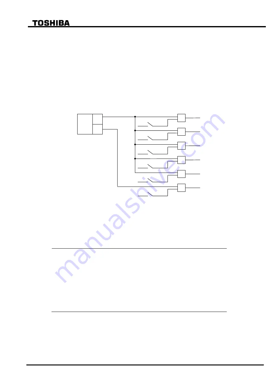
Figure 2.6.1 shows the scheme logic of thermal overcurrent protection. THR tripping output can
be given to up to five breakers. Any of the five breaker tripping signals THR-1 to THR-5 can be
blocked by the scheme switch [THR1] to [THR5] settings. Alarming signal THR-A can be
blocked by the scheme switch [THRA] setting.
THR
A
S
THR-1
&
[THR1]
THR-2
&
[THR2]
THR-3
&
[THR3]
THR-4
&
[THR4]
THR-5
&
[THR5]
THR-A
&
[THRA]
“ON”
“ON”
“ON”
“ON”
“ON”
“ON”
Figure 2.6.1 Scheme Logic of Thermal Overload Protection
Setting
The following shows the setting elements for the thermal overload protection and their setting
ranges.
Element
Range
Step
Default
Remarks
0.5
500.0min
0.1min
60.0min
Thermal time constant
k
0.10
4.00
0.01
1.30
Constant
IB
0.50
2.50(*1)
0.01
1.00
Basic current
Ip
0.00
1.00(*1)
0.01
0.00
Pre-specified load current
TA
0
10min
1min
10min
Time for alarm (before trip) (*3)
Scheme switch
THR1 to THR5
THRA
Off/On
Off/On
(*2)
On
Enable or disable
Trip
Alarm
(
1): Multiplier of CT secondary rated current
(*2): Default settings are dependent on the models. See Appendix H.
(*3):
Alarming time = THR trip time (operating time)
TA (setting time)
Note: Ip sets a minimum level of previous load current to be used by the thermal element, and is
typically used when testing the element. For the majority of applications, Ip should be set to
zero, in which case the previous load current, Ip, is calculated internally by the thermal
model, providing memory of conditions occurring before an overload.
Содержание GRT100 Series
Страница 55: ... 54 6 F 2 S 0 7 8 9 TRANSFORMER PROTECTION GRT100 Operation keys 101B 21 11 Figure 3 1 9 Front Panel ...
Страница 142: ... 141 6 F 2 S 0 7 8 9 Appendix A Block Diagram ...
Страница 144: ... 143 6 F 2 S 0 7 8 9 Appendix B Signal List ...
Страница 159: ... 158 6 F 2 S 0 7 8 9 ...
Страница 160: ... 159 6 F 2 S 0 7 8 9 Appendix C Variable Timer List ...
Страница 162: ... 161 6 F 2 S 0 7 8 9 Appendix D Binary Output Default Setting List ...
Страница 165: ... 164 6 F 2 S 0 7 8 9 ...
Страница 166: ... 165 6 F 2 S 0 7 8 9 Appendix E Details of Relay Menu and LCD and Button Operation ...
Страница 174: ... 173 6 F 2 S 0 7 8 9 Appendix F Case Outline Flush Mount Type Rack Mount Type ...
Страница 179: ... 178 6 F 2 S 0 7 8 9 ...
Страница 180: ... 179 6 F 2 S 0 7 8 9 Appendix G External Connections ...
Страница 185: ... 184 6 F 2 S 0 7 8 9 ...
Страница 200: ... 199 6 F 2 S 0 7 8 9 ...
Страница 201: ... 200 6 F 2 S 0 7 8 9 Appendix J Return Repair Form ...
Страница 205: ... 204 6 F 2 S 0 7 8 9 Customer Name Company Name Address Telephone No Facsimile No Signature ...
Страница 206: ... 205 6 F 2 S 0 7 8 9 ...
Страница 207: ... 206 6 F 2 S 0 7 8 9 Appendix K Technical Data ...
Страница 220: ... 219 6 F 2 S 0 7 8 9 ...
Страница 221: ... 220 6 F 2 S 0 7 8 9 Appendix M Symbols Used in Scheme Logic ...
Страница 224: ... 223 6 F 2 S 0 7 8 9 ...
Страница 225: ... 224 6 F 2 S 0 7 8 9 Appendix N Implementation of Thermal Model to IEC60255 8 ...
Страница 228: ... 227 6 F 2 S 0 7 8 9 ...
Страница 229: ... 228 6 F 2 S 0 7 8 9 Appendix O IEC60870 5 103 Interoperability and Troubleshooting ...
Страница 241: ... 240 6 F 2 S 0 7 8 9 Appendix P Modbus Interoperability ...
Страница 255: ... 254 6 F 2 S 0 7 8 9 ...
Страница 256: ... 255 6 F 2 S 0 7 8 9 Appendix Q Inverse Time Characteristics ...
Страница 259: ... 258 6 F 2 S 0 7 8 9 ...
Страница 260: ... 259 6 F 2 S 0 7 8 9 Appendix R Failed Module Tracing and Replacement ...
Страница 266: ... 265 6 F 2 S 0 7 8 9 Appendix S Ordering ...
Страница 269: ... 268 6 F 2 S 0 7 8 9 3 1 Oct 2 2017 Republished under spin off company ...
Страница 270: ......


