


130
6
F
2
S
0
7
8
9
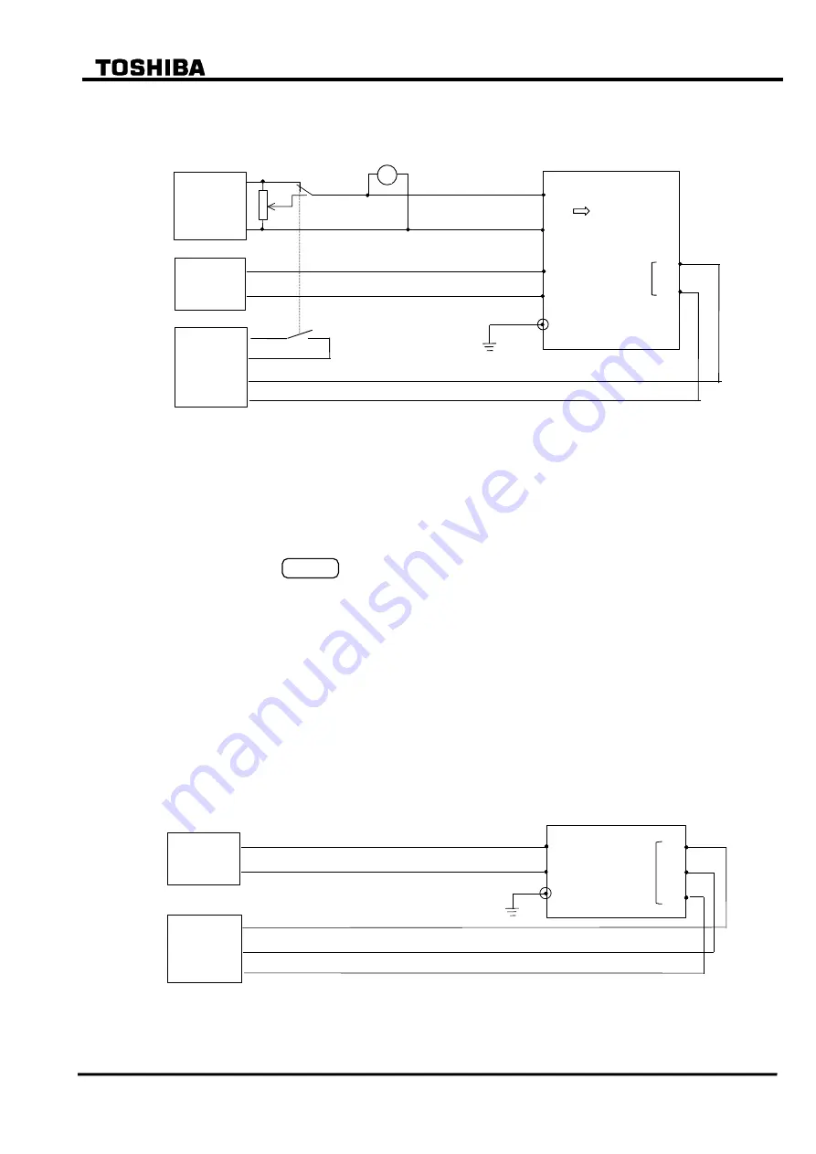
Operating time characteristic test
The testing circuit is shown in Figure 6.5.15.
Single-phase
voltage
source
TB 1 -27
-28
V
GRT100
Monitoring
jack
A
0V
E
TB 4 - A16
- A17
DC
power
supply
Start
Time
counter
OV
Stop
V
Figure 6.5.15 Operating Time Characteristic Test of V/F (Model 100s, 200s)
The testing procedure is as follows:
Press 4 (= Logic circuit) on the "Test" sub-menu screen to display the "Logic circuit"
screen.
Enter a signal number 81 to observe the inverse time tripping output at monitoring jack A
and press the
ENTER
key.
Apply a test voltage at rated frequency and measure the operating time. The magnitude of
the test voltage should be between (V setting)
(L setting) and (V setting)
(H setting).
Calculate the theoretical operating time using the characteristic equations shown in
Section 2.11.8 where V is the test voltage. Check that the measured operating time is from
15% to
10% of the calculated value.
6.5.2 Timer Test
The pick-up delay time of the variable timer can be measured by connecting the monitoring jacks
A and B to a time counter as shown in Figure 6.5.15. Jacks A and B are used to observe the input
signal and output signal of the timer, respectively.
TB 4 - A16
- A17
E
GRT100
DC
power
supply
Monitoring
jack
A
0V
B
Time
counter
Start
Stop
0V
Figure 6.5.16 Testing Variable Timer (Model 100s, 200s)
Содержание GRT100 Series
Страница 55: ... 54 6 F 2 S 0 7 8 9 TRANSFORMER PROTECTION GRT100 Operation keys 101B 21 11 Figure 3 1 9 Front Panel ...
Страница 142: ... 141 6 F 2 S 0 7 8 9 Appendix A Block Diagram ...
Страница 144: ... 143 6 F 2 S 0 7 8 9 Appendix B Signal List ...
Страница 159: ... 158 6 F 2 S 0 7 8 9 ...
Страница 160: ... 159 6 F 2 S 0 7 8 9 Appendix C Variable Timer List ...
Страница 162: ... 161 6 F 2 S 0 7 8 9 Appendix D Binary Output Default Setting List ...
Страница 165: ... 164 6 F 2 S 0 7 8 9 ...
Страница 166: ... 165 6 F 2 S 0 7 8 9 Appendix E Details of Relay Menu and LCD and Button Operation ...
Страница 174: ... 173 6 F 2 S 0 7 8 9 Appendix F Case Outline Flush Mount Type Rack Mount Type ...
Страница 179: ... 178 6 F 2 S 0 7 8 9 ...
Страница 180: ... 179 6 F 2 S 0 7 8 9 Appendix G External Connections ...
Страница 185: ... 184 6 F 2 S 0 7 8 9 ...
Страница 200: ... 199 6 F 2 S 0 7 8 9 ...
Страница 201: ... 200 6 F 2 S 0 7 8 9 Appendix J Return Repair Form ...
Страница 205: ... 204 6 F 2 S 0 7 8 9 Customer Name Company Name Address Telephone No Facsimile No Signature ...
Страница 206: ... 205 6 F 2 S 0 7 8 9 ...
Страница 207: ... 206 6 F 2 S 0 7 8 9 Appendix K Technical Data ...
Страница 220: ... 219 6 F 2 S 0 7 8 9 ...
Страница 221: ... 220 6 F 2 S 0 7 8 9 Appendix M Symbols Used in Scheme Logic ...
Страница 224: ... 223 6 F 2 S 0 7 8 9 ...
Страница 225: ... 224 6 F 2 S 0 7 8 9 Appendix N Implementation of Thermal Model to IEC60255 8 ...
Страница 228: ... 227 6 F 2 S 0 7 8 9 ...
Страница 229: ... 228 6 F 2 S 0 7 8 9 Appendix O IEC60870 5 103 Interoperability and Troubleshooting ...
Страница 241: ... 240 6 F 2 S 0 7 8 9 Appendix P Modbus Interoperability ...
Страница 255: ... 254 6 F 2 S 0 7 8 9 ...
Страница 256: ... 255 6 F 2 S 0 7 8 9 Appendix Q Inverse Time Characteristics ...
Страница 259: ... 258 6 F 2 S 0 7 8 9 ...
Страница 260: ... 259 6 F 2 S 0 7 8 9 Appendix R Failed Module Tracing and Replacement ...
Страница 266: ... 265 6 F 2 S 0 7 8 9 Appendix S Ordering ...
Страница 269: ... 268 6 F 2 S 0 7 8 9 3 1 Oct 2 2017 Republished under spin off company ...
Страница 270: ......