background image

42

DeviceNet Module Installation and Operation Manual

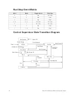
Run/Stop Event Matrix 

Control Supervisor State Transition Diagram 

Run1

Run2

Trigger Event

Run Type 

0

0

Stop

No Action 

 1

0

Run

Run1 

0

 1

Run

Run2 


1

 1

No Action

No Action 

1

1

No Action

No Action 

 0

1

Run

Run2 

1

 0

Run

Run1

Non-Existent

Startup

Not_Ready

Ready

Enabled

Stopping

Stop

Stop

Run

Main Power On

Main Power Off

Initialization Complete

Fault Detected

Fault Reset

Fault Detected

Fault Detected

Faulted

Complete

Fault_Stop

Complete

Fault_Stop

Main Power Off

Switch Off

Switch On

Reset

Содержание DEV002Z

Страница 1: ...Installation and Operation Manual ASD OPTIONAL DEVICENET MODULE ...

Страница 2: ......

Страница 3: ...ASD Optional DeviceNet Module DEV002Z Installation and Operation Manual Document Number 58683 000 Date January 2008 ...

Страница 4: ... details or variations in equipment types Nor may it provide for every possible contingency concerning the installation operation or maintenance of this equipment Should additional information be required contact your Toshiba representative The contents of this manual shall not become a part of or modify any prior or existing agreement commitment or relationship The sales contract contains the ent...

Страница 5: ...RNATIONAL CORPORATION DEV002Z DeviceNet Module Please complete the Warranty Card supplied with the DeviceNet Module option card and return it to Toshiba by prepaid mail This will activate the 12 month warranty from the date of installation but shall not exceed 18 months from the shipping date Complete the following information and retain for your records Model Number ______________________________...

Страница 6: ... are used throughout the manual Read the manual completely before installing operating performing maintenance or disposing of this equipment This manual and the accompanying drawings should be considered a permanent part of the equipment and should be readily available for reference and review Dimensions shown in the manual are in metric and or the English equivalent Because of our commitment to c...

Страница 7: ...icator 10 Message Size 10 Polled I O Messaging Connection 10 Explicit Messaging Connection 10 Communications Parameters 11 Example F830 2 Instance 100 150 12 DeviceNet Local Remote Operation 15 Object Specifications 16 Identity Object 16 Identity Object Specific Services 17 Message Router Object 18 Message Router Specific Services 18 DeviceNet Object 19 Assembly Object 20 Assembly Object Specific ...

Страница 8: ...3 FE36 Analog Input Value V I 34 FE37 RX Input 34 FE60 to FE63 My Function Monitor 1 4 34 FE14 Cumulative Run Time 34 FE40 Analog Output FM 34 FE41 Analog Output AM 34 FC91 Alarm Code 34 FD06 Input Terminal Board Status 35 FD07 Output Terminal Board Status 35 Connection Object 36 Connection Class Specific Services 39 Motor Data Object 39 Motor Data Object Specific Services 40 Control Supervisor Ob...

Страница 9: ...UTION are used in this manual they will be followed by important safety information that must be carefully adhered to The word DANGER preceded by the safety alert symbol indicates that an imminently hazardous situation exists that if not avoided will result in death or serious injury to personnel The word WARNING preceded by the safety alert symbol indicates that a potentially hazardous situation ...

Страница 10: ... manual Qualified Personnel Installation operation and maintenance shall be performed by Qualified Personnel Only A Qualified Person is one that has the skills and knowledge relating to the construction installation operation and maintenance of the electrical equipment and has received safety training on the hazards involved Refer to the latest edition of NFPA 70E for additional safety requirement...

Страница 11: ...ed location and preferably in the original carton if the equipment will not be used upon receipt Store in a cool clean and dry location within the temperature range of 13 to 150 F 25 to 65 C Do not store the unit in places that are exposed to outside weather conditions rapid temperature changes high humidity moisture dust corrosive gases or metal particles Disposal Do not dispose of electrical com...

Страница 12: ...l and Maintenance Precautions Do not install the DeviceNet module if it is damaged or if it is missing any component s Turn off lockout and tagout the main power the control power and instrumentation connections before inspecting or servicing the ASD or opening the door of the enclosure Turn off lockout and tagout the main power the control power and instrumentation connections before proceeding t...

Страница 13: ...configuration software A maximum of 62 follower devices can be connected to the network Check Accessories The DeviceNet module card is shipped with the following items in the package Contact your sales representative if any of these is missing ASD ASD ASD ASD DeviceNet module DEV002Z 1 card DeviceNet open connector connected 1 connector Installation and Operation Manual for DEV002Z DeviceNet optio...

Страница 14: ...nal on the connector is given below Table 1 Pinouts for DeviceNet Connector 1 Use shielded wire for the control signal wires 2 Use wire size 22 16 AWG 0 3 1 5 mm2 3 Strip 0 28 in 7 mm of insulation off the end of the connecting wire 4 Use a small slotted standard screwdriver to tighten the connector lug screws 5 Tighten the connector lug screws Torque the lug screws to 4 4 5 3 in lb 0 5 0 6 N m Co...

Страница 15: ...rner of the front panel forward to dis engage the retention tab Repeat for the other side Remove the front panel b Install the option card by fitting the curved tabs on the bottom of the option into the slots at the bottom of the ASD Or I O Expansion Card if installed c Ensure that the option card closes over the ASD I O Expansion Card alignment tabs Press the option card closed and ensure that th...

Страница 16: ...eters are set cycle the power to the ASD for these changes to take effect Network Ground Observe the following precautions when installing a DeviceNet network ground Do not connect the G E terminal to a power ground or any other potential noise producing ground connection such as the E terminal of the ASD Connect to a close clean ground to provide RF termination of the DeviceNet cable Do not make ...

Страница 17: ... 0010 18 01 0010 34 10 0010 50 11 0010 3 00 0011 19 01 0011 35 10 0011 51 11 0011 4 00 0100 20 01 0100 36 10 0100 52 11 0100 5 00 0101 21 01 0101 37 10 0101 53 11 0101 6 00 0110 22 01 0110 38 10 0110 54 11 0110 7 00 0111 23 01 0111 39 10 0111 55 11 0111 8 00 1000 24 01 1000 40 10 1000 56 11 1000 9 00 1001 25 01 1001 41 10 1001 57 11 1001 10 00 1010 26 01 1010 42 10 1010 58 11 1010 11 00 1011 27 01...

Страница 18: ... Fault OR Connection Time Out Recoverable fault has been detected One or more I O Connections are in the Timed Out state Steady Red Critical Fault OR Critical Link Failure The DeviceNet module has an unrecoverable fault and may need replacing because of a failed communication device The DeviceNet module has detected an error that has rendered it incapable of communicating on the network Duplicate ...

Страница 19: ...eviceNet card supports both the standard DeviceNet AC Drive profile Instances 20 70 21 71 and user defined Instances 100 150 101 151 and 102 152 Parameter Function Adjustment Range Default Setting F8301 Communication Option DeviceNet Profibus Setting 0 Instance 20 70 1 Instance 21 71 2 Instance 100 150 3 Instance 101 151 4 Instance 102 152 5 6 7 0 F851 ASD Operation at Disconnect Action to be carr...

Страница 20: ...ference Speed Hz High byte 1 Byte Bit7 Bit6 Bit5 Bit4 Bit3 Bit2 Bit1 Bit0 0 DC Braking Acc Dec 1 2 PI Control Motor 1 2 Reserved Alarm FC91 Fault Fault FL 1 Reserved Ready without ST Run Ready with ST Run Emergency Off Coast to Stop ST Run Stop Forward Reverse Jog 2 Drive Speed Hz Low byte 3 Drive Speed Hz High byte Byte Bit Specifications 0 1 Supplement 0 0 Preset Speed 1 1 Preset Speed 0000 Off ...

Страница 21: ...og Run Frequency 1 1 Forward Run Reverse Run Forward Run Reverse Run 1 2 Run Stop Stop Run 1 3 Coast to Stop Ready for Operation Coast to Stop 1 4 Emergency Off Off Emergency Off If 1 is specified error tripping can occur 1 5 Reset Off Reset Enabled only in the event of tripping 1 6 Frequency Link Off Priority Enabled Overrides the setting of F004 1 7 Command Link Off Priority Enabled Overrides th...

Страница 22: ...been restored 4 Emergency Off The error message err8 is displayed Commands entered through the net work are not canceled When communications are restored the ASD must be reset to in order to clear the error message and resume normal operation 5 Preset Speed The ASD uses the Preset Speed selection referenced in F852 Refer to Preset Speed Operation Selection Network commands will be processed once c...

Страница 23: ...Figure 2 Wiring for Local Remote Operation Parameter setting F003 Command Mode 0 Terminal Block F004 Frequency Mode 1 2 RR F112 Input Terminal 2 R Function 48 Remote Local control Operation R CC open The ASD functions as a follower device on DeviceNet R CC closed F CC Close to Run F CC Open to Stop Output frequency is set by the RR signal input ASD PP CCA F R CC RR SW1 DeviceNet Local switch Opera...

Страница 24: ...gned 16 bit integer value UINT Unsigned 16 bit integer value UDINT Unsigned 32 bit integer value Identity Object Class code 0x01 This object provides identification of and general information about the device Table 9 Identity Object Class Attributes Class Code Object Class Page 0x01 Identity Object pg 16 0x02 Message Router Object pg 18 0x03 DeviceNet Object pg 19 0x04 Assembly Object pg 20 0x05 C...

Страница 25: ...Major USINT ARRAY Get Revision of the item the Identity Object represents 100 1 Revision Minor USINT ARRAY Get 1 2 5 Status bits sup ported WORD Get Summary status of device 6 Serial Number UDINT Get Serial number of device 7 Product Name SHORT_ STRING Get Alphanumeric product identification DEV002Z 8 State USINT Get Present state of the device 0 Non existent 1 Device Self Testing 2 Standby 3 Oper...

Страница 26: ...es Description Default Value 1 Revision UINT Get Revision of this object 1 2 Max Instance UINT Get Maximum instance number of an object currently created in this class level of the device 1 Attribute ID Name Data Type Access Rules Description Default Value 1 Object List USINT ARRAY Get A list of supported objects 2 Number Available UINT Get Maximum number of connections supported 1 3 Number Active...

Страница 27: ...e 0 125 kbps 1 250 kbps 2 500 kbps 01 3 Bus off Interrupt BOOL Get Set Bus Off Interrupt 0 4 Bus off Counter USINT Get Set Number of times CAN went to the bus off state 0 5 Allocation Informa tion Allocation Choice Byte BYTE Get Master Follower allocation state Allocation Informa tion Master s MAC ID USINT Get MAC ID of Master from Allocate 6 MAC ID Switch Changed BOOL Get The MAC Address switch s...

Страница 28: ...ined Master Follower Connection Set 0x4C Release_group_2_identifier _set N A Yes Indicates that the specified connections within the Predefined Master Follower Connection Set are no longer required and are to be released Attribute ID Name Data Type Access Rules Description Default Value 1 Revision UINT Get Revision of this object 2 2 Max Instance UINT Get Maximum instance number of an object curre...

Страница 29: ... Bit 1 Bit 0 0 Fault Reset Run Forward 1 2 Drive Reference Speed rpm Low byte 1 3 Drive Reference Speed rpm High byte 1 Byte Bit 7 Bit 6 Bit 5 Bit 4 Bit 3 Bit 2 Bit 1 Bit 0 0 Running Forward Faulted Tripped 1 2 Drive Speed rpm Low byte 3 Drive Speed rpm High byte Instance Byte 15 14 13 12 11 10 9 8 7 6 5 4 3 2 1 0 Hex Output Instance 20 1 0 0 0 0 0 0 0 0 0 0 0 0 0 0 0 0 0 0x0000 3 2 Input Instance...

Страница 30: ...t When Run Stop command from DeviceNet is enabled 1 is set Bit 6 Ref from Net When frequency command from DeviceNet is enabled 1 is set Bit 7 At Reference When output frequency equals the frequency command 1 is set 3 Drive Status is same as the Control Supervisor class State attribute See pg 40 Control Supervisor Object Instance Attributes 1 Startup 5 Stopping 7 Faulted 2 Not Ready 7 Enabled 3 Rea...

Страница 31: ...0 0 0 0 0 0 0 0 0 0 0 0 0 0 0 0 0x0000 Instance Byte 15 14 13 12 11 10 9 8 7 6 5 4 3 2 1 0 Hex Output Instance 21 1 0 0 0 0 0 0 0 0 0 0 1 1 0 0 0 0 1 0x0061 3 2 0 0 0 0 0 1 1 1 0 0 0 0 1 0 0 0 0x0708 Input Instance 71 1 0 0 0 0 0 0 1 0 0 1 1 1 1 0 1 1 0 0x04F6 3 2 0 0 0 0 0 1 1 1 0 0 0 0 1 0 0 0 0x0708 Instance Byte 15 14 13 12 11 10 9 8 7 6 5 4 3 2 1 0 Hex Output Instance 21 1 0 0 0 0 0 0 0 0 0 0...

Страница 32: ... Hz unit 6000 units 0x1770 Table 34 Input Instance 150 Layout Examples of Instance 100 150 Table 35 Instance 100 150 Stop Byte Bit 7 Bit 6 Bit 5 Bit 4 Bit 3 Bit 2 Bit 1 Bit 0 0 DC Braking Accel 1 Accel 2 PI Off THR2 Preset Speed4 Preset Speed3 Preset Speed2 Preset Speed1 1 Command Link 1 Frequency Link 1 Reset trip Emergency Off Coast ST Run Stop Forward Reverse Jog 2 Drive Reference Speed Hz Low ...

Страница 33: ...0 0 0 1 0 1 1 1 0 1 1 1 0 0 0 0 0x1770 Instance Byte 15 14 13 12 11 10 9 8 7 6 5 4 3 2 1 0 Hex Output Instance 100 1 0 1 1 0 0 0 1 1 0 0 0 0 0 0 0 0 0 0xC600 3 2 0 0 0 1 0 1 1 1 0 1 1 1 0 0 0 0 0x1770 Input Instance 150 1 0 0 1 1 0 0 1 1 0 0 0 0 0 0 0 0 0 0x6600 3 2 0 0 0 1 0 1 1 1 0 1 1 1 0 0 0 0 0x1770 Instance Byte 15 14 13 12 11 10 9 8 7 6 5 4 3 2 1 0 Hex Output Instance 100 1 0 1 0 0 0 0 1 0 ...

Страница 34: ... 15 set to 0 Table 42 Instance 101 151 Read Parameter F003 Command mode selection Communication number is 0003 4 Index Low byte 5 Write Index High byte 6 Data Low byte 7 Data High byte Byte Bit 7 Bit 6 Bit 5 Bit 4 Bit 3 Bit 2 Bit 1 Bit 0 0 At Reference Ref from Net Ctrl from Net Ready Running Reverse Running Forward Warning Faulted Tripped 1 Drive Status 1 2 Drive Speed rpm Low byte 3 Drive Speed ...

Страница 35: ...x0268 7 6 Input Instance 151 F268 set to 60 0 Hz 5 4 0 0 0 0 0 0 1 0 0 1 1 0 1 0 0 0 0x0268 7 6 0 0 0 1 0 1 1 1 0 1 1 1 0 0 0 0 0x1770 Instance Byte 15 14 13 12 11 10 9 8 7 6 5 4 3 2 1 0 Hex Output Instance 101 5 4 0 0 1 1 1 1 1 0 0 0 0 0 0 1 0 0 0x3E04 7 6 Input Instance 151 FE04 set to 94 49 5 4 0 0 1 1 1 1 1 0 0 0 0 0 0 1 0 0 0x3E04 7 6 0 0 1 0 0 1 0 0 1 1 1 0 1 0 0 1 0x24E9 Instance Byte 15 14...

Страница 36: ...d data High byte 6 F834 Command data Low byte 7 F834 Command data High byte 8 F835 Command data Low byte 9 F835 Command data High byte 10 F836 Command data Low byte 11 F836 Command data High byte Byte Bit 7 Bit 6 Bit 5 Bit 4 Bit 3 Bit 2 Bit 1 Bit 0 0 F841 Monitor data Low byte 1 F841 Monitor data High byte 2 F842 Monitor data Low byte 3 F842 Monitor data High byte 4 F843 Monitor data Low byte 5 F8...

Страница 37: ... parameter F831 If 0xC400 is entered here 0xC400 will be written as the value of FA06 Example 2 State monitoring by the input instance 152 To monitor the output current set parameter F841 to 3 FD03 The value of the parameter FD03 is specified as byte 0 and 1 of the input instance 152 ASD F833 DEV002Z Output Instance 102 DeviceNet Master Value Byte 3 2 1 0 C4 00 F832 F831 1 FA06 C4DD is set as para...

Страница 38: ... 1 FD01 ASD status 1 2 FD00 Output frequency 0 01 Hz 3 FD03 Output current 0 01 4 FD05 Output voltage 0 01 5 FC91 ASD alarm 6 FD22 PID feedback value 0 01 Hz 7 FD06 Input terminal status 8 FD07 Output terminal status 9 FE36 V I input 10 FE35 RR input 11 FE37 RX input 12 FD04 Input voltage DC detection 0 01 13 FD16 Speed feedback real time value 14 FD18 Torque 0 01 15 FE60 My monitor 16 FE61 My mon...

Страница 39: ...Priority When Enabled this overrides the parameter F003 Bit Function 0 1 Note 0 Speed Torque Speed Control Torque Control 1 Clear kWh Off Clear Clear the value of FE76 FE77 2 Reserved 3 Brake Close BC Normal Forced Close 4 Pre Magnetic Normal On 5 Brake Open B Brake Close Brake Open 6 Brake Answer BA Brake Close Brake Open 7 Fast Stop Normal On 8 Accel 1 Accel 2 00 Acc Dec 1 01 Acc Dec 2 10 Acc De...

Страница 40: ...can output to AM terminal The data adjustment range is 0 2047 resolution 11 bits Select 31 analog output for communication as AM terminal meter selection parameter before using it Refer to the Meter Setting and Adjustment section of the ASD instruction manual for details FD00 Output Frequency real time The current output frequency is read to a resolution of 0 01 Hz per Hex unit For example when th...

Страница 41: ...ormation for the motor connected to the ASD is input into parameters F405 F415 the 100 torque monitor value becomes the same as the rated torque of the motor FE35 Analog Input Value RR Read the RR terminal input The value range is 0x0000 0x2710 0 100 00 Bit Function 0 1 Note 0 FL No Output Active Output 1 Emgergency No Fault Active Fault The retry status and the trip reten tion status are also reg...

Страница 42: ...ad the output value of the FM terminal The value range is 0 65535 0xFFFF FE41 Analog Output AM Read the output value of the AM terminal The value range is 0 65535 0xFFFF FC91 Alarm Code Bit Function 0 1 Note 0 Over Current Alarm Normal Active alarm C blinking 1 ASD Overload Alarm Normal Active alarm L blinking 2 Motor Overload Alarm Normal Active alarm L blinking 3 Over Heat Alarm Normal Active al...

Страница 43: ... Input TB Function select 9 F119 9 LI2 Input TB Function select 10 F120 10 LI3 Input TB Function select 11 F121 11 LI4 Input TB Function select 12 F122 12 LI5 Input TB Function select 13 F123 13 LI6 Input TB Function select 14 F124 14 LI7 Input TB Function select 15 F125 15 LI8 Input TB Function select 16 F126 Bit TB Name Function Parameter 0 1 0 OUT1 Output TB Function select 1 F130 Off On 1 OUT2...

Страница 44: ...on pg 36 Explicit Messaging Connection Object Instance Attributes Instance 1 2 Reference on pg 37 Poll Connection Object Instance Attributes Instance 2 Attribute ID Name Data Type Access Rules Description Default Value 1 State USINT Get State of the object 00 Non existent 01 Configuring 02 Waiting for connection ID 03 Established 04 Timed Out 05 Deferred Delete 2 Instance_type USINT Get Indicates ...

Страница 45: ...mpty 15 Received_connection_path _length UINT Get Number of bytes in received_connection_path attribute 0 16 Received_connection_path USINT ARRA Y Get Specifies Application Object s whose data is to be received by this connec tion Empty Service Code Service Name Supported Class Supported Instance Description of Service 0x05 Reset N A Yes Used to reset all resettable connection objects 0x0E Get_att...

Страница 46: ...Trnsmitted_connection_path _length UINT Get Number of bytes in transmitted_connection_path attribute 6 14 Transmitted_connection _path USINT ARRAY Get Specifies Application Object s whose data is to be transmitted by this connection 0x20 0x04 0x24 0x46 0x30 0x03 Instance 70 15 Received_connection_path _length UINT Get Number of bytes in received_connection_path attribute 6 16 Received_connection_p...

Страница 47: ...he attribute ID number of the last instance attribute of the class definition implemented in the device 15 Attribute ID Name Data Type Access Rules Description Default Value 1 Number of Attributes USINT Get Number of attributes supported 7 2 Attributes List USINT ARRAY Get List of attributes supported 3 Motor Type USINT Get 0 Non standard Motor 1 PM DC Motor 2 FC DC Motor 3 PM Synchronous Motor 4 ...

Страница 48: ...tribute 0x10 Set_attribute_single N A Yes Modifies the value of the specified attribute Attribute ID Name Data Type Access Rules Description Default Value 1 Revision UINT Get Revision of this object 1 2 Max Instance UINT Get Maximum instance number of an object currently created in this class level of the device 1 6 Max ID of Class Attributes UNIT Get The attribute ID number of the last class attr...

Страница 49: ...ning 2 BOOL Get 1 Enabled and Run2 OR Stopping and Running2 OR Fault_Stop and Running2 0 Other state 9 Ready BOOL Get 1 Ready OR Enabled OR Stopping 0 Other state 10 Faulted BOOL Get 1 Fault Occurred latched 0 No Faults present 11 Warning BOOL Get 1 Warning not latched 0 No Warnings present 12 Fault Reset BOOL Get Set 0 1 Fault Reset 0 No action 15 Control From Net USINT Get Status of Run Stop con...

Страница 50: ... 0 Run Run1 0 0 1 Run Run2 0 1 0 1 No Action No Action 1 1 No Action No Action 1 0 1 Run Run2 1 1 0 Run Run1 Non Existent Startup Not_Ready Ready Enabled Stopping Stop Stop Run Main Power On Main Power Off Initialization Complete Fault Detected Fault Reset Fault Detected Fault Detected Faulted Complete Fault_Stop Complete Fault_Stop Main Power Off Switch Off Switch On Reset ...

Страница 51: ... Rules Description Default Value 1 Number of Attributes USINT Get Number of Attributes supported 16 2 Attribute List USINT ARRAY Get List of Attributes supported 3 At Reference BOOL Get Denotes if ASD Speed Actual Attrib 7 is at Speed Reference Attrib 8 in speed control mode or if Torque Actual Attrib 11 is at Power Actual Attrib 15 in torque control mode 0 ASD speed torque not at reference value ...

Страница 52: ...h Speed Limit Units ms 20 Low Speed Limit UINT Get Set Minimum speed limit Units rpm 21 High Speed Limit UINT Get Set Maximum speed limit Units rpm 26 Power Scale SINT Get Power scaling factor 29 Ref From Net BOOL Get Status of torque speed reference 0 Local torque speed reference 1 DeviceNet torque speed reference 46 Drive Power On Hours DINT Get Total number of hours drive has had power applied ...

Страница 53: ...a Communication Number 0x0268 0x0268 0x4000 0x4268 The Instance ID for F268 is 0x4268 Example 3 The Monitor parameter FE03 Output current has Communication Number 0x3E03 0x3E03 0x4000 0x7E03 FE03 becomes Instance ID 7E03 Note The Monitor parameter can access Get only Instance ID and Parameter Values Set F009 Acceleration time to 5 sec The incremental unit is 0 1 sec unit The value in F009 is 5 sec...

Страница 54: ...l number DEV002Z Use environment Indoors at an altitude of 9800 ft 3000 m or less where the product will not be exposed to direct sunlight corrosive or explosive gases vapor coarse particulates including dust and where there is no grinding fluid or grinding oil nearby Ambient temperature 14 140 F 10 60 C Storage temperature 13 149 F 25 65 C Relative humidity 20 93 non condensing Vibration 0 6 G 5 ...

Страница 55: ......

Страница 56: ...INDUSTRIAL DIVISION 13131 West Little York Road Houston Texas 77041 Tel 713 466 0277 Fax 713 466 8773 US 800 231 1412 Canada 800 872 2192 Mexico 01 800 527 1204 www toshiba com ind Printed in the U S A ...

Отзывы: