22
DeviceNet Module Installation and Operation Manual
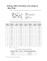
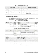
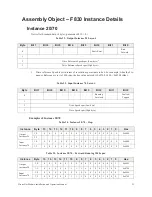
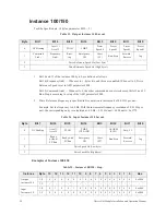
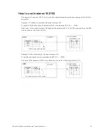
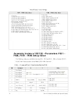
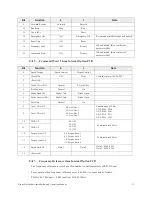
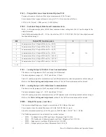
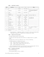
Table 26. Instance 20/70 – Fault Reset.
1
1 – Fault reset triggers on 0 to 1 transition only.
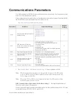
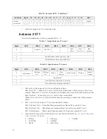
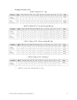
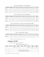
Instance 21/71
DeviceNet Standard data. (4 bytes, parameter F830 = 1)
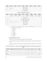
Table 27. Output Instance 21 Layout.
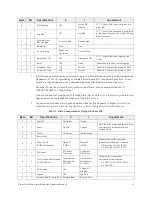
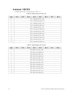
Table 28. Input Instance 71 Layout.
1 – Bit 5 and 6 of the instance 21 byte 0 are defined as follows.
Bit 5 (Net Ctrl) — When bit 5 is set to 1, bits 0 (Run forward) and 1 (Run reverse) of byte 0 are
enabled. When bit 5 is set to 0 is set, Run/Stop is dictated by the setup of the ASD parameter F003.
Bit 6 (Net Ref) — When bit 6 is set to 1, bytes 2 and 3 are enabled.
When bit 6 is set to 0 is set, Drive Reference Speed is according to setup of the ASD parameter
F004.
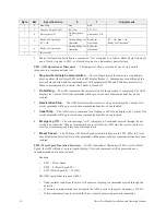
2 – Bit 5, 6, and 7 of the instance 71 byte 0 are defined as follows.
Bit 5 (Ctrl from Net) — When Run/Stop command from DeviceNet is enabled, 1 is set.
Bit 6 (Ref from Net) — When frequency command from DeviceNet is enabled, 1 is set.
Bit 7 (At Reference) — When output frequency equals the frequency command, 1 is set.
3 – Drive Status is same as the Control Supervisor class State attribute (See
).
1 — Startup
5 — Stopping
7 — Faulted
2 — Not Ready
7 — Enabled
3 — Ready
6 — Fault Stop
Instance
Byte
15
14
13
12
11
10
9
8
7
6
5 4 3
2
1
0
Hex
Output
Instance 20
1, 0
0
0
0
0
0
0
0
0
0
0
0
0
0
1
0
0
0x0004
3, 2
-
-
-
-
-
-
-
-
-
-
-
-
-
-
-
-
-
Byte
Bit 7
Bit 6
Bit 5
Bit 4
Bit 3
Bit 2
Bit 1
Bit 0
0
-
Net Ref
1
Net Ctrl
1
-
-
Fault
Reset
Run
Reverse
Run
Forward
1
-
2
Drive Reference Speed rpm (Low byte)
3
Drive Reference Speed rpm (High byte)
Byte
Bit 7
Bit 6
Bit 5
Bit 4
Bit 3
Bit 2
Bit 1
Bit 0
0
At Reference
2
Ref from
Net
2
Ctrl from
Net
2
Ready
Run
Reverse
Run Forward
Warning
Faulted/
Tripped
1
Drive Status
3
2
Drive Reference Speed rpm (Low byte)
3
Drive Reference Speed rpm (High byte)
Содержание DEV002Z
Страница 1: ...Installation and Operation Manual ASD OPTIONAL DEVICENET MODULE ...
Страница 2: ......
Страница 55: ......


