5-29
Digital Edition - TIMECUTTER® HD Service Manual
April 2017
CHASSIS
Chassis
Park Brake Handle Assembly
Removal
1. Park the machine on a level surface and disengage the PTO. Stop the engine, wait for all moving parts to stop,
and remove key.
2. Disconnect the battery terminals.
3. Remove the left side console,
see “Left Console Removal,” chapter 5, page 5-6.
4. Re-install the fuel cap.
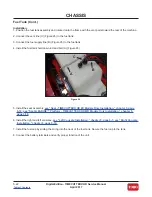
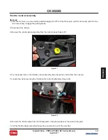
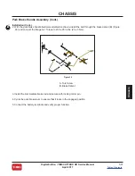
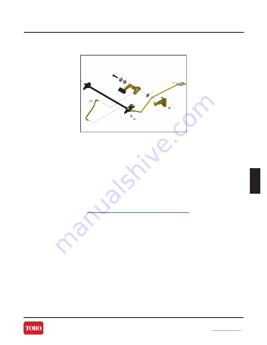
5. Remove the locking cotter pin (A) securing the intermediate brake rod (B) (Figure 36) to the park brake lever.
6. Remove the bolt and flange nut (G) from the park brake lever assembly. Retain the bushing (D) and wave
spring (E) (Figure 36).
A
B
C
D
E
F
G
Figure 36
A. Cotter Pin
B. Intermediate Brake Rod
C. Torx Screw
D. Flange Bushing
E. Wave Spring
F. Brake Flanged Bushing
G. Flange Nut
Содержание TIMECUTTER HD 74864
Страница 153: ...R e s i d e n t i a l P r o d u c t s ...


