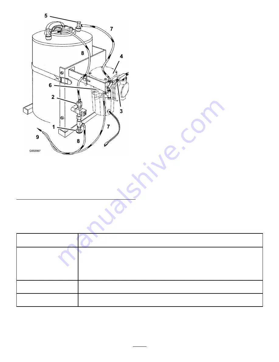
background image

Figure 33

1.

Foam density adjustment
valve

6.

Air filter

2.

Strainer

7.

Air only

3.

Check valve

8.

Liquid

4.

Compressor

9.

To mixer tee

5.

Couplers

9. Start operating the marking system and make a test

pattern on the ground. When you first start the
marking system, allow 1 to 2 minutes for the foam
to flow through the line.

10. Adjust the foam density adjustment valve to obtain

the desired consistency and spray as normal.

Note:

If you leave the foam in the line for more

than 2 hours, it may become watery. Before
operating after a break of 2 or more hours, run the
machine for 1 to 2 minutes to remove the excess
water.

Note:

The mixer tee can flood if the solution-to-air

mixture is too rich, producing watery foam. If the
foam is too dry, the flow will be unsteady with
high-pressure surges.

If the foam in the machine is very watery, do the
following:

A. Close the foam density adjustment valve

completely.

B. Operate for 2 minutes.

C. Wait 1 minute and then check the consistency

of the foam.

D. Adjust the foam to achieve the desired

consistency.

Maintenance

Recommended Maintenance Schedule(s)

Maintenance Service

Interval

Maintenance Procedure

Every 100 hours

• Inspect the hose between the foam tank and the compressor for accumulated water.
• Inspect and clean the check valve in the tee on top of the compressor. Replace

the valve if necessary.

• Remove and clean the strainer at the top of the solenoid valve, next to the

compressor.

• Ensure that the bottom of the compressor is free from debris.

Every 250 hours

• Replace the compressor air filter.
• Check for and rinse out debris from the inside of the tank.

Every 500 hours

• Replace the plastic check valve at the “Y” near the mixer tee assembly, located at

the rear of the machine, on the center boom.

Cleaning the Strainer

Important:

Dried foam agent and debris can

clog the strainer (Figure 34), causing slow or no

foam production. This can be mistaken for a bad
foam pump or incorrect foam mix. If experiencing

15

Содержание 41228

Страница 1: ...ons Note If you are installing this kit on a machine equipped with a cab a bracket from Custom Products part number 2 15904 needs to be installed as well to eliminate the interference with the cab Not...

Страница 2: ...Install the tank compressor and mixer Bolt 3 8 x 1 inch 1 Locknut 3 8 inch 1 Mixer assembly 1 2 Flat washer 3 8 inch 2 Install the mixer tee Wiring harness 1 Hose clamp small 6 3 Plastic ties 12 Wire...

Страница 3: ...ter bracket to the right side of the vehicle above the battery Figure 1 using 4 carriage bolts 3 8 x 1 1 4 inches and 4 flange locknuts 3 8 inch Note It is easiest if you remove the battery before per...

Страница 4: ...Figure 4 1 Tank compressor assembly 3 Bolt 3 8 x 1 inch 2 Multi Pro 1200 series adapter bracket 4 Flat washer 3 8 inch Multi Pro 5600 5700 Turf Sprayer 1 Remove 4 bolts 1 4 x 1 inch and flat washers...

Страница 5: ...the cover and fasteners aside 3 Mark a 108 inch supply hose with a black marker at each end Figure 9 Figure 9 1 Compressor hose 3 To the mixer tee 2 Needle valve hose 4 Connect the marked supply hose...

Страница 6: ...rough the Workman adapter bracket and cover into the tank compressor assembly Figure 11 12 Remove the left handle and fasteners from the left side of the tank skid Save fasteners for later use 13 Moun...

Страница 7: ...ft supply hose to the left side solenoid assembly 7 Secure both hoses with small hose clamps Figure 14 For all sprayers serial number 260000001 and higher 1 At the rear of the machine mount the mixer...

Страница 8: ...plug the harness connectors into the boom solenoid assemblies Plug the connector with the blue wire to the right solenoid plug the connector with the orange wire to the left solenoid Figure 18 Figure...

Страница 9: ...of the sprayer Figure 22 A Plug the connector with the yellow blue wire into the left boom solenoid B Plug the connector with the blue green wire into the right boom solenoid Figure 22 1 Mixer tee ass...

Страница 10: ...e assembly Figure 25 Figure 25 1 Control panel 3 Foam marker switches 2 Latch 3 Remove the foam marker switch hole plugs 4 Install the 2 rocker switches into the switch panel Note Ensure that the notc...

Страница 11: ...cal 2 Fuse block 5 Completing the Installation Parts needed for this procedure 2 Boom hose 2 Grommet 2 Punched hole boom cap 2 Extension hose 2 Hose clamp large 1 Parts catalog Procedure For all spray...

Страница 12: ...the punched hole boom cap until it extends 2 to 3 inches past the cap Figure 29 8 Install the boom cap into the end of the boom pipe Figure 29 9 Lubricate the inside of the extension hose and slide it...

Страница 13: ...h the punched hole boom cap until it extends 2 to 3 inches past the cap Figure 31 Figure 31 1 Top bar boom frame 4 Hose clamp 2 Boom hose 5 Extension hose 3 Cap 6 Assembled 5 Install the boom cap onto...

Страница 14: ...Density 1 Ensure that both the left and right boom switches located on the console are in the Off position The contents of the foam marker tank are under pressure Loosening the fittings on the tank c...

Страница 15: ...justment valve completely B Operate for 2 minutes C Wait 1 minute and then check the consistency of the foam D Adjust the foam to achieve the desired consistency Maintenance Recommended Maintenance Sc...

Страница 16: ...d assembly Figure 34 1 Hose barb 4 Nozzle adapter 2 Nozzle body 5 Solenoid assembly 3 Strainer 6 Liquid hose 5 Inspect and clean strainer Replace if necessary 6 Assemble strainer and nozzle body hose...

Отзывы: