19-13
19 TOP FIELD MODE
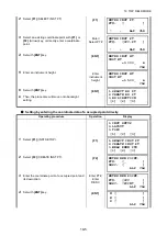
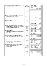
19.4.2To Layout
Operating procedure
Operation
Display
1
Select
{F2}
(LAYOUT).
{F2}
2
Enter a reflector height.
Enter
reflector
height
3
Set with
{ENT}
key.
{ENT}
4
Select a coordinate point to layout with
{F1}
or
{F2}
(Arrow) key, or enter a coordinate point
directly.
Enter/
Select PT#
5
Set with
{ENT}
key. The data displayed will be
Line 1: Horizontal angle to layout point
(Difference)
Line 2: Cross directional distance to layout point
(Difference)
Line 3: Vertical distance to layout point
(Difference)
{ENT}
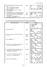
6
Pressing
{F1}
(MSR) will perform distance
measurement and it will also display the distance
difference.
Data is updated each time (MSR) is performed.
{F1}
7
Pressing
{F2}
(R/L) key will display distance
difference in the horizontal direction, instead of the
difference in the horizontal angle.
Line 1: Horizontal distance to layout point
(Difference)
Line 2: Cross directional distance to layout point
(Difference)
Line 3: Vertical distance to layout point
(Difference)
{F2}
1.INST SETUP
2.LAYOUT
3.TOPO
[1] [2] [3]
ENTER TARGET HT
HT OF ROD
=0.000_ m
CLR
ENTER TARGET HT
HT OF ROD
=1.500_ m
CLR
ENTER LAYOUT POINT#
PT#: [_ ]
DESC: [ ]
↑
↓
ALP CLR
ENTER LAYOUT POINT#
PT#: [P01_ ]
DESC: [ ]
↑
↓
ALP CLR
dHA: 45°00'00"
IN : m
CUT: m
MSR R/L REC NEXT
dHA: 45°00'00"
IN : 2.500 m
CUT: 0.010 m
MSR R/L REC NEXT
R : 1.250 m
IN : 2.500 m
CUT: 0.010 m
MSR NEZ REC NEXT

