18-7
18 CHECKS AND ADJUSTMENTS
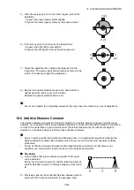
5) When the survey point is on the lower (upper) part of the
illustration:
1. Loosen the upper (lower) screw slightly.
2. Tighten the lower (upper) screw by the same amount.
6) If the survey point is on the solid line (dotted line):
3. Loosen the right (left) screw slightly.
4. Tighten the left (right) screw by the same amount.
7) Check the adjustment by rotating the upper part of the
instrument. The survey point should remain centered in the
reticle. If necessary, repeat the adjustment.
8) Remove the optical plummet knob cover, and install the
optical plummet reticle cover on the inside.
Replace the optical plummet knob cover.
•
Do not over-tighten the 4 adjusting screws as this may cause the reticle to go out of adjustment.
18.6 Additive Distance Constant
The additive distance constant K of the ES is adjusted to 0 before delivery. Although it almost never
deviates, use a baseline with a known distance precision to check that the additive distance constant K
is close to 0 several times a year and whenever the values measured by the instrument begin to
deviate by a consistent amount. Perform these checks as follows.
•
Errors in setting up the instrument and reflective prism or in sighting the target will influence the
additive distance constant. Be extremely careful to prevent such errors when performing these
procedures.
•
Set up so that the instrument height and the target height are identical. If a flat place is not
available, use an automatic level to make sure the heights are identical.
Checking
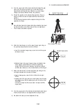
1) Find an area of flat ground where two points 100m apart
can be selected.
Set up the Instrument at point A and the reflective prism at
point B. Establish a point C half way between points A and
B.
2) Precisely measure the horizontal distance between point A
and point B 10 times and calculate the average value.
1 (2)
2 (1)
4
(3)
3
(4)


