background image

9-16

9  MEMORY MANAGER MODE

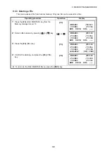
9.7.2 Loading Data

Coordinate data files and PCODE Library data can be loaded from PC.
Example: Loading a coordinate data file (from PC)

Operating procedure

Operation

Display

1

Press the 

{F3}

 (MEMORY MGR.) key from the

menu 1/3.

{F3}

2

Press the 

{F4}

 (P

) key twice.

{F4}
{F4}

3

Press the 

{F1}

 (DATA TRANSFER) key.

{F1}

4

Press the 

{F2}

 (RS-232C) key.

{F2}

5

Press the 

{F4}

 (ENTER) key.

{F4}

6

Press the 

{F1}

 (GTS FORMAT) key.

{F1}

7

Press the 

{F2}

 (LOAD DATA) key.

{F2}

8

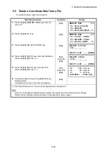
Select the type of data to load by pressing

{F1}

 or 

{F2}

 key.

Example: 

{F1}

 (COORD. DATA)

{F1}

9

Enter New File Name you want to receive. Press 
the 

{F4}

 (ENT) key. *1)

Enter FN

{F4}

10

Press the 

{F3}

 (YES) key.*2)

The loading starts.
The display will return to menu.

{F3}

*1)

Refer to Section 2.4 “How to Enter Alphanumeric Characters”.

*2) To cancel the loading, press the 

{F4}

 (STOP) key.

MEMORY MGR.      1/3
 F1:FILE STATUS
 F2:SEARCH
 F3:FILE MAINTAN  P

MEMORY MGR.      3/3
 F1:DATA TRANSFER
 F2:INITIALIZE
                  P

SELECT COM
 [F1:BLUETOOTH]
  F2:RS-232C
  F3:USB       ENTER

DATA TRANSFER
 F1:GTS FORMAT
 F2:SSS FORMAT

DATA TRANSFER
 F1:SEND DATA
 F2:LOAD DATA
 F3:COMM. PARAMETERS

LOAD DATA
 F1:COORD. DATA
 F2:PCODE DATA

COORD. FILE NAME
 FN=_________
 
[ALP][SPC][CLR][ENT]

LOAD COORD. DATA
 
 >OK ?
 –––  –––  [YES][NO]

LOAD COORD. DATA

    < Loading Data!>
               STOP

Содержание ES-62

Страница 1: ...ES 62 ES 65 EASY STATION INSTRUCTION MANUAL 1016312 01 B...

Страница 2: ...any form or by any means This manual may not be modified adapted or otherwise used for the production of derivative works Symbols The following conventions are used in this manual Indicates precautio...

Страница 3: ...combustible materials An explosion could occur Do not perform disassembly or rebuilding Fire electric shock burns or hazardous radiation exposure could result Never look at the sun through the telesco...

Страница 4: ...ly insulating tape or equivalent to the terminals Otherwise shorting could occur resulting in fire or burns Do not use batteries or the battery charger if wet Resultant shorting could lead to fire or...

Страница 5: ...r Otherwise the pacemaker may be adversely affected by the electromagnetic waves produced and cease to operate as normal Do not use onboard aircraft The aircraft instrumentation may malfunction as a r...

Страница 6: ...attery cover and external interface hatch and correctly attach the connector caps to protect the ES from moisture and dust particles Make sure that moisture or dust particles do not come in contact wi...

Страница 7: ...ts battery and place it in the case in accordance with the layout plan Consult your local dealer before using the instrument under special conditions such as long periods of continuous use or high lev...

Страница 8: ...lace within the vicinity of portable premises radio equipment or specified low power radio equipment In the case that the instrument causes radio interference with portable premises radio equipment te...

Страница 9: ...unications regulations Wireless communication module is incorporated in the instrument Use of this technology must be compliant with telecommunications regulations of the country where the instrument...

Страница 10: ...r intentionally point the laser beam at another person The laser beam is injurious to the eyes and skin If an eye injury is caused by exposure to the laser beam seek immediate medical attention from a...

Страница 11: ...e Laser pointer function be sure to turn OFF the emission of the laser beam Only those who have been received training as per the following items shall use this product Read the Operator s manual for...

Страница 12: ...2 Setting a Horizontal Angle from the Keys 3 3 3 4 Vertical Angle Percent Grade Mode 3 3 3 5 Repetition Angle Measurement 3 4 3 6 Buzzer Sounding for Horizontal Angle 90 Increments 3 5 3 7 Compasses v...

Страница 13: ...of DATA COLLECT 7 7 7 2 1 Searching the recorded data 7 8 7 2 2 Entering PCODE ID using PCODE Library 7 8 7 2 3 Entering PCODE ID from the list of PCODE 7 9 7 3 Data Collect Offset Measurement mode 7...

Страница 14: ...nserting the USB flash drive 15 1 16 DETACH ATTACH OF TRIBRACH 16 1 17 SELECTING MODE 17 1 17 1 Items of the Selecting Mode 17 1 17 2 How to Set Selecting Mode 17 3 18 CHECKS AND ADJUSTMENTS 18 1 18 1...

Страница 15: ...21 SPECIAL ACCESSORIES 21 1 22 BATTERY SYSTEM 22 1 23 PRISM SYSTEM 23 1 24 ERROR DISPLAYS 24 1 25 REGULATIONS 25 1 26 SPECIFICATIONS 26 1 APPENDIX APPENDIX 1 Target for Laser plummet adjustment APPEND...

Страница 16: ...e eyepiece screw 27 Telescope focussing ring 28 Sighting collimator 29 Instrument center mark Sighting collimator Use sighting collimator to aim the ES in the direction of the measurement point Turn t...

Страница 17: ...and illumination of display window are adjusted See Chapter 6 SPECIAL MODE Menu Mode or section 1 5 Star key mode Example Angle measurement mode V angle 90 10 20 H angle 120 30 40 Distance measuremen...

Страница 18: ...h can be communicated by Bluetooth E E coordinate Z Z coordinate Keys Name of Key Function Star key Switches to Star key mode This mode is used for each presetting or displaying as follows 1 Contrast...

Страница 19: ...SC Escape key Returns to the measurement mode or previous layer mode from the mode set Switches to data collection mode or layout mode directly from the normal measurement mode It is also possible to...

Страница 20: ...s a measuring mode Fine Coarse Tracking F3 NP P Switches non prism mode prism mode or sheet mode F4 P1 The function of soft keys is shown on next page P2 2 F1 OFSET Select Off set measurement mode F2...

Страница 21: ...een For levelling procedure see Section 2 5 2 Levelling key Display mark Function F1 Turn the Laser plummet option ON OFF F2 Setting Tilt Correction If ON the display shows tilt correction value F3 Tu...

Страница 22: ...he point indicated by the laser pointer The distance to which the laser pointer can be used will vary with climatic conditions and with the eyesight of the user When the laser pointer is used the oper...

Страница 23: ...ts above Output at the tracking mode is displayed as distance data only The details necessary for the connection with the ES are obtained from the ES 60 series Interface Manual which is optionally ava...

Страница 24: ...correction value PPM and you can also adjust the contrast of the display when the instrument is turned on To display this screen see Chapter 17 SELECTING MODE This enables you to adjust the brightnes...

Страница 25: ...power level regarding to the measurement mode now operating The safety condition indicated by the battery power remaining display in the angle measurement mode does not necessarily assure the battery...

Страница 26: ...X and Y directions The display of Vertical or Horizontal angle is unstable when instrument is on an unstable stage or a windy day You can turn off the auto tilt correction function of V H angle in th...

Страница 27: ...selected the display shows tilt correction value F1 3 Press F3 OFF key F3 4 Press ESC key ESC The setting mode performed here will not be memorized after powering OFF To set TILT correction in the ini...

Страница 28: ...the characters displayed above the key in the order they are listed Decimal point key Plus minus sign key Input a decimal point plus or minus sign during numeric input During alphabetic input input t...

Страница 29: ...ical input mode 3 Press the F1 ALP key The instrument switches to alphabetical input mode 4 Enter letters of the alphabet by pressing the alphanumeric characters key Example 1 STU key is pressed twice...

Страница 30: ...the F1 NUM key again The instrument switches back to numerical input mode 7 Enter numbers by pressing the alphanumeric characters key Example 1 key is pressed 8 Press F4 ENT key The arrow moves to nex...

Страница 31: ...spaced at equal intervals and the head is approximately level Set the tripod so that the head is positioned over the survey point Make sure the tripod shoes are firmly fixed in the ground 2 Place the...

Страница 32: ...press F1 The laser plummet beam will be emitted from the bottom of the instrument 5 Use to adjust the brightness of the laser 6 Adjust the levelling foot screws to align the laser beam with the cente...

Страница 33: ...he inside circle is 4 and the range of the outside circle is 6 Tilt angle values X and Y are also displayed on the screen is not displayed when the tilt of the instrument exceeds the detection range o...

Страница 34: ...ten the centering screw securely When the instrument was centered using the laser plummet emit the plummet beam again to check position over the survey point See PROCEDURE Centering with the laser plu...

Страница 35: ...your eye is focussed at infinity 2 Loosen the vertical and horizontal clamps then use the sighting collimator to bring the target into the field of view Tighten both clamps 3 Turn the telescope focus...

Страница 36: ...diopter ring toward you first and then backward to focus 2 Aim the target at the peak of the triangle mark of the sighting collimator Allow a certain space between the sighting collimator and yourself...

Страница 37: ...time pressing the F2 R L key HR HL mode switches Operating procedure Operation Display 1 Set the required horizontal angle using Horizontal tangent screw Display angle 2 Press the F2 HOLD key F2 3 Co...

Страница 38: ...e required Horizontal angle is possible 70 4020 F4 1 To enter Alphanumeric characters see Section 2 4 How to Enter Alphanumeric Characters Operating procedure Operation Display 1 Press the F4 key to g...

Страница 39: ...te target A using the horizontal clamp and tangent screw and press the F3 REL key Collimate A F3 8 Recollimate target B using the horizontal clamp and tangent screw and press the F4 HOLD key Collimate...

Страница 40: ...izontal angle can be accumulated up to 3600 00 00 minimum reading horizontal angle right In case of 5 second reading horizontal angle can be accumulated up to 3599 59 55 Error will be displayed when t...

Страница 41: ...ating procedure Operation Display 1 Press the F4 key twice to get the function on page 3 F4 twice 2 Press the F3 CMPS key 1 F3 1 Every time pressing the F3 CMPS key the display mode switches 90 90 0 0...

Страница 42: ...an be selected depending on the object to measure prism mode non prism mode objects other than prism and sheet mode Regardless of whether the laser pointer is used measurement is possible with both th...

Страница 43: ...t starts 1 2 The measured distances are shown 3 5 Pressing the key again the display changes to horizontal HR and vertical V angle and slope distance SD 6 1 When EDM is working the mark appears in the...

Страница 44: ...ss F1 MEAS key while continuous measuring is exceeding 2 The average value is displayed and mark disappears F1 While EDM is working press F1 MEAS key again the mode will be changed to continuous measu...

Страница 45: ...time than in fine mode The unit to be displayed can be changed To change the unit to be displayed in fine mode see Chapter 17 SELECTING MODE and to change the unit in course mode see section 6 4 1 Set...

Страница 46: ...ssing the F1 to F3 key Example Horizontal distance F1 4 Enter the distance for stake out 1 Enter data F4 5 Collimate the target Prism Measuring starts Collimate P The difference between the measured d...

Страница 47: ...result display Refer to Chapter 17 SELECTING MODE to set this option Distance measurement mode of the offset measurement Offset measurement will be done by N time fine measurement mode For setting mea...

Страница 48: ...OFFSET key F1 4 Collimate prism P and press the F1 MEAS key Collimate P F1 Prism P Prism height Instrument height Occ Point When measuring coordinates of ground point A1 Set the instrument height pris...

Страница 49: ...and slope distance are shown in sequence 8 Show N coordinate of point A0 or A1 Each time pressing key N E and Z coordinate are shown in sequence To return to procedure 4 press the F1 NEXT key To retur...

Страница 50: ...Press the F1 OFSET key F1 3 Press the F2 DIST OFFSET key F2 4 Enter Right and Left direction offset value and press the F4 ENTER key Enter HD F4 5 Enter Forward direction offset value and press the F4...

Страница 51: ...on and slope distance are shown in sequence Show coordinate of point P0 To return to procedure 4 press F1 NEXT key To return to the previous mode press ESC key Press the F3 NP P key after the step 3 t...

Страница 52: ...tion 5 1 Setting Coordinate Values of Occupied Point Example Non prism measurement Operating procedure Operation Display 1 Press the F4 P1 key from distance measuring mode to get the function on page...

Страница 53: ...ress the key 9 To escape the measuring press the F1 EXIT key The display returns to the previous mode 1 In case the calculation of plane was not successful by the measured three points error displays...

Страница 54: ...occupied station refer to Section 5 1 Setting Coordinate Values of Occupied Point Example Non prism measurement Operating procedure Operation Display 1 Press the F4 P1 key from distance measuring mode...

Страница 55: ...nd press the F4 SET key Collimate P3 F4 The distance between the instrument and center of the column P0 will be calculated 9 To show the relative elevation VD press the key Each time pressing the key...

Страница 56: ...e coordinate measurement mode to get the function on page 2 F4 2 Press the F3 OCC key F3 3 Enter N coordinate value 1 Enter data F4 4 Enter E and Z coordinate values in the same manner After entering...

Страница 57: ...ters Input range 999 9999 Instrument height 999 9999 m 999 999 Instrument height 999 999 ft 999 11 7 Instrument height 999 11 7 ft inch Operating procedure Operation Display 1 Press the F4 key from th...

Страница 58: ...z Coordinates of unknown point N1 E1 Z1 N1 N0 n E1 E0 e Z1 Z0 INS HT z R HT Operating procedure Operation Display 1 Set the direction angle of known point A 1 2 Collimate target prism Set direction a...

Страница 59: ...ee Chapter 7 DATA COLLECTION See Chapter 8 LAYOUT See Chapter 9 MEMORY MANAGER MODE F1 F2 F3 PROGRAMS 1 2 F1 REM F2 MLM F3 Z COORD P GRID FACTOR 1 000000 MODIFY YES NO ILLUMINATION ON 1 F1 ON F2 OFF F...

Страница 60: ...g procedure Operation Display 1 After pressing the MENU key press the F4 P key to get the menu on page 2 MENU F4 2 Press the F2 key F2 3 Press the F1 REM key F1 4 Press the F1 key 5 Enter prism height...

Страница 61: ...e Operation Display 1 After pressing the MENU key press the F4 P key to get the menu on page 2 MENU F4 2 Press the F2 key F2 3 Press the F1 REM key F1 4 Press the F2 key F2 5 Collimate prism Collimate...

Страница 62: ...f point G will be decided 1 F4 9 Collimate target K Vertical distance VD will be shown 2 Collimate K 1 To return to procedure 5 press the F3 HD key To return to procedure 7 press the F2 V key 2 To ret...

Страница 63: ...ry to set the direction angle of the instrument Example MLM 1 A B A C Procedure of MLM 2 A B B C mode is completely same as MLM 1 mode Operating procedure Operation Display 1 After pressing the MENU k...

Страница 64: ...how slope distance dSD press key 10 To measure the distance between points A and C press the F3 HD 1 F3 11 Collimate point C Prism C and press the F1 MEAS key Horizontal distance HD between the instru...

Страница 65: ...e coordinate data file select USE FILE in step 4 After procedure 6 1 Press the F3 NEZ key Direct key input display will be shown F3 2 Press the F3 PT key to use coordinate data file Point number input...

Страница 66: ...Press the F1 USE FILE key 5 Press the F1 INPUT key and enter the File Name F1 F1 Enter FN F4 6 Press the F1 key F1 7 Press the F1 INPUT key and enter the Point number Instrument height setting displa...

Страница 67: ...coordinate data file F1 Enter PT F4 8 Press the F3 YES key and enter the Point Number in coordinate data file F3 9 Enter the height Enter R HT F4 10 Collimate a prism on the point and press the F1 ME...

Страница 68: ...4 13 Press the F3 YES key Horizontal angle will be set The display returns to Programs 1 2 menu F3 1 Measurement is Fine N times measurement mode 2 To measure other points press the F1 NEXT key 3 Pres...

Страница 69: ...splay 1 After pressing the MENU key press the F4 P key to get the menu on page 2 4 MENU F4 2 Press the F2 key F2 3 Press the F4 P key to get the PROGRAMS menu on page 2 2 F4 4 Press the F1 AREA key F1...

Страница 70: ...to get the PROGRAMS menu on page 2 2 F4 4 Press the F1 AREA key F1 5 Press the F2 MEASUREMENT key F2 6 Press the F1 or F2 key to select using GRID FACTOR Example F2 DON T USE F2 7 Collimate a prism an...

Страница 71: ...t will be shown 1 Measurement is Fine N times measurement mode Operating procedure Operation Display 1 Press the F3 UNIT key F3 2 Select a unit by pressing the F1 to F4 key Example F2 ha key F2 m sq s...

Страница 72: ...ay 1 After pressing the MENU key press the F4 P key to get the menu on page 2 4 MENU F4 2 Press the F2 key F2 3 Press the F4 P key to get the PROGRAMS menu on page 2 2 F4 4 Press the F2 key F2 5 Enter...

Страница 73: ...limate P2 F1 10 Press F1 NEZ key to measure other points 11 Collimate a prism and press F1 MEAS key Coordinate measurement starts 4 The result will be shown 5 F1 Collimate P F1 1 Measurement is Fine N...

Страница 74: ...istance HDg in order to reverse convert grid distance to ground distance 2 After completion of a layout point the displayed coordinate data will be applied to grid factor in order to compare with surv...

Страница 75: ...9 999 meter 32 805 to 3 2805 ft ft in Scale Factor 0 990000 to 1 010000 Operating procedure Operation Display 1 After pressing the MENU key press the F4 P key twice to get the menu on page 3 MENU F4 F...

Страница 76: ...mode To select minimum display for fine measurement mode see Chapter 17 SELECTING MODE Example Minimum angle 5 Coarse 1mm Models Angle Unit Coarse mode Distance unit Degree GON MIL ES 62 65 5 1 1mgon...

Страница 77: ...To return to previous mode press the ESC key Operating procedure Operation Display 1 After pressing the MENU key press the F4 P key twice to get the menu on page 3 MENU F4 F4 2 Press the F2 key F2 3 P...

Страница 78: ...ion Display 1 After pressing the MENU key press the F4 P key twice to get the menu on page 3 MENU F4 F4 2 Press the F2 key F2 3 Press the F3 key The data previously set is shown If already ON the disp...

Страница 79: ...6 21 6 SPECIAL MODE Menu Mode 4 Press the F1 key The data previously set is shown F1 5 Press the F1 ON key or F2 OFF key and press the F4 ENTER key F1 or F2 F4 ERROR CORR OFF F1 ON F2 OFF ENTER...

Страница 80: ...y setting Baud rate 1200 baud rate Character bit Parity 7 Even CRLF OFF REC type REC A ACK Standard Operating procedure Operation Display 1 After pressing the MENU key press the F4 P key twice to get...

Страница 81: ...F4 2 Press the F2 key F2 3 Press the F4 key F4 4 Press the F3 key F3 5 Press the F1 BLUETOOTH key to select the communication port and press the F4 ENTER key The display will return to the previous m...

Страница 82: ...actory default setting is NONE Operating procedure Operation Display 1 After pressing the MENU key press the F4 P key twice to get the menu on page 3 MENU F4 F4 2 Press the F2 key F2 3 Press the F4 ke...

Страница 83: ...erating procedure Operation Display 1 After pressing the MENU key press the F4 P key three times to get the menu on page 3 MENU F4 F4 F4 2 Press the F2 key F2 3 Press the F1 key or F2 key and press th...

Страница 84: ...R POINT 04 N 0 000 m E 0 000 m INPUT ENTER DATA SEARCH F1 FIRST DATA F2 LAST DATA LINE 01 30 L 100 000 m AZ 45 00 00 EDIT OCC BS F1 OCC BS F2 RESECTION OCC BS F1 COORD DATA F2 ROAD DATA SETOUT ROAD CH...

Страница 85: ...ut value data CHAIN INTERVAL 6 Press the ENT key Input data ENT For ROAD in addition to the Start Point and Road Data input files other files necessary for the calculations are created Consequently if...

Страница 86: ...t only the maximum is 9 points including end point An error may occur when entering a combination of POINT and other components if the amount of data entered exceeds the maximum amount allowed for int...

Страница 87: ...y 4 Input LENGTH 5 Press the ENT key 6 Select TURN direction of turn RIGHT or LEFT 7 Press the ENT key Input RADIUS ENT Input LENGTH ENT Select F1 LEFT or F2 RIGHT ENT 1 CURVE cannot be input as the f...

Страница 88: ...HT or LEFT 7 Press the ENT key Input RADIUS ENT Input LENGTH ENT Select F1 LEFT or F2 RIGHT ENT 8 Select DIR direction IN entrance or OUT exit 9 Press the ENT key Select F1 IN or F2 OUT ENT 1 SPIRAL c...

Страница 89: ...T Input E coord ENT Input RADIUS ENT Input parameter A1 ENT Input parameter A2 ENT 1 If the data input is not required press the SKIP key When inputting POINT data if the next data is not POINT data R...

Страница 90: ...2 F4 2 Press the F3 F1 F2 F2 key Refer to Search data on page 6 26 F3 F1 F2 F2 3 To search from the first data select F1 FIRST DATA F1 4 To switch to different data press the or key or Operating proce...

Страница 91: ...the data from Coord Data and set the Occupied Point ROAD DATA Create the data from Road Data and set the Occupied Point Example ROAD DATA F2 5 Input OCC PT press the ENT key Input OCC PT ENT 6 Press...

Страница 92: ...ss the F3 YES key F3 1 When setting the Occupied Point and Backsight Point using Resection method select F2 RESECTION For details of the Resection method refer to Section 8 3 2 Resection Method BACKSI...

Страница 93: ...ngle of the layout point HD Calculated horizontal distance from the instrument to the layout point F3 9 Press the F1 ANG key CHAIN Layout point HR Measured Actual horizontal angle dHR Horizontal angle...

Страница 94: ...y Refer to Select a file on page 6 26 F3 F2 3 Press the F3 key 4 Enter the name of the file being used or select it from the list 5 Press the ENT key F3 Select a file ENT Operating procedure Operation...

Страница 95: ...cause the internal memory covers both data collection mode and layout mode the number of measurement points will be decreased when the layout mode is used For the internal memory refer to Chapter 9 ME...

Страница 96: ...ng occupied point See Section 7 1 3 Occupied Point and Backsight Point BACKSIGHT Setting direction angle See Section 7 1 3 Occupied Point and Backsight Point FS SS Executing data collection See sectio...

Страница 97: ...TER key The file will be set and data collect 1 2 menu will be shown F4 1 If you want to make a new file or input file name directly press F1 INPUT key and enter a file name 2 When a file has been sel...

Страница 98: ...data collect menu 2 2 beforehand Operating procedure Operation Display 1 Press the F1 SELECT A FILE key from DATA COLLECT menu 2 2 F1 2 Press the F2 COORD DATA key F2 3 Select a coordinate file in th...

Страница 99: ...e internal memory Operating procedure Operation Display 1 Press the F1 OCC PT INPUT key from the data collect menu 1 2 The previous data is shown F1 2 Press the F4 OCNEZ key F4 3 Press the F1 INPUT ke...

Страница 100: ...s memorized and the display returns to the data collect menu 1 2 Collimate BS F2 1 Pressing each time the F3 key the input method changes as Coordinate value Angle Coordinate point name alternatively...

Страница 101: ...PT is automatically incremented F2 7 Enter the next point data and collimate the next point Collimate 8 Press F4 ALL key Measuring starts in the same measuring mode of the previous point Data is recor...

Страница 102: ...e executing the DATA COLLECT mode press F2 SRCH key 1 The using file name will appear on the top of the right side of the display F2 2 Select one of three search methods by pressing F1 to F3 key 2 F1...

Страница 103: ...e or decrease or Increasing or Decreasing one by one or By ten Increasing or Decreasing 1 or or 3 Press the F4 ENTER key F4 1 To edit the PCODE library press the F1 EDIT key To delete the PCODE regist...

Страница 104: ...ress the F3 MEAS key and press the F4 key to get to the next soft key page F3 F4 2 Press the F1 OFSET key F1 3 Press the F1 ANG OFFSET key F1 4 Collimate the prism Collimate P Prism P Prism height Ins...

Страница 105: ...Show N coordinate of point A0 or A1 Each time pressing key N E and Z coordinate are shown in sequence 10 Press the F3 YES key The data is recorded and the next measuring point is displayed F3 OFFSET...

Страница 106: ...Operation Display 1 Press the F3 MEAS key and press the F4 key to get to the next soft key page F3 F4 2 Press the F1 OFSET key F1 3 Press the F2 DIST OFFSET key F2 4 Enter Right and Left direction off...

Страница 107: ...P 7 Press the F2 or F3 key Example F3 NEZ key Measuring starts The data is recorded and the next measuring point is displayed F3 1 To skip entering press the F3 SKP key PT PT 11 PCODE TOPCON R HT 1 2...

Страница 108: ...ion axis and of the plane Operating procedure Operation Display 1 Press the F3 MEAS key and press the F4 key to get to the next soft key page F3 F4 2 Press the F1 OFSET key F1 3 Press the F3 PLANE OFF...

Страница 109: ...mber will be displayed F3 10 To escape the measuring press the ESC key The display returns to the next point number in data collect mode ESC 1 In case the calculation of plane was not successful by th...

Страница 110: ...F3 MEAS key and press the F4 key to get to the next soft key page F3 F4 2 Press the F1 OFSET key F1 3 Press the F4 P1 key F4 4 Press the F1 COLUMN OFFSET key F1 5 Collimate the center of the column P1...

Страница 111: ...new data by confirming display Coordinates will be calculated using the grid factor To set the grid factor see Section 6 2 Setting the GRID FACTOR 6 Collimate the left side of the column P2 and press...

Страница 112: ...F4 4 Enter the point 1 data and press the F4 Enter The input screen of a reference point 2 will appear Input data F4 5 Enter the point 2 data and press the F4 Enter The screen will return to data coll...

Страница 113: ...a is calculated the PTL data will be displayed regardless of the coordinate check setting etc F2 3 PTL measurement data will display Confirm the data and press F3 YES key The recorded data are measure...

Страница 114: ...nu 2 2 F2 2 By pressing the following keys the list will increase or decrease or Increasing or Decreasing one by one or By ten Increasing or Decreasing or or 3 Press the F1 EDIT key F1 4 Enter PCODE a...

Страница 115: ...is recorded F2 COLLECT SEQ EDIT MEAS MEAS EDIT Select the procedure of data collection EDIT MEAS Measurement is carried out after entering other data MEAS EDIT Measurement is carried out before enteri...

Страница 116: ...he measured data and the coordinate data for layout Maximum 30 files can be generated The number of coordinate data In case not using the internal memory in the data collect mode Because the internal...

Страница 117: ...KP If you do not want to create or reselect a file F4 ENTER To select display file LAYOUT 1 2 F1 OCC PT INPUT F2 BACKSIGHT F3 LAYOUT P LAYOUT MENU 1 2 ESC F1 F2 F3 LAYOUT 2 2 F1 SELECT A FILE F2 NEW P...

Страница 118: ...way Grid Factor is displayed for 1 to 2 second and display returns to Layout menu 2 2 Enter Scale F4 1 Refer to Section 2 4 How to Enter Alphanumeric Characters Input Range Elevation 9 999 to 9 999 me...

Страница 119: ...display the list of coordinate data file 1 F2 3 Scroll file list by pressing the or key and select a file to use 2 3 or 4 Press the F4 ENTER key The file will be set F4 1 If you want to input file nam...

Страница 120: ...e Operating procedure Operation Display 1 Press the F1 OCC PT INPUT key from the Layout menu 1 2 F1 2 Press the F1 INPUT key and enter PT 1 Press the F4 ENT key F1 Enter PT F4 3 Enter INS HT in the sa...

Страница 121: ...INPUT key and enter PT Press the F4 ENT key 2 F1 Enter PT F4 5 Enter Instrument Height in the same way The display returns to layout menu 1 2 Enter INS HT F4 1 Refer to Section 2 4 How to Enter Alphan...

Страница 122: ...y 1 Press the F2 BACKSIGHT key from the Layout menu 1 2 F2 2 Press the F1 INPUT key Enter PT press the F4 ENT key 1 F1 Enter PT F4 3 Sight the backsight point and press the F3 YES key The display retu...

Страница 123: ...nter coordinate value Press the F4 ENT key 1 2 F1 Enter coord F4 4 Sight the backsight point Sight BK 5 Press the F3 YES key The display returns to the layout menu 1 2 F3 1 Refer to Section 2 4 How to...

Страница 124: ...Measured Actual horizontal angle dHR Horizontal angle to be turned to the layout point Actual horizontal angle Calculated horizontal angle Correct direction when dHR 0 00 00 Collimate P F1 5 Press th...

Страница 125: ...xt layout point PT is automatically incremented F4 1 Refer to Section 2 4 How to Enter Alphanumeric Characters 2 Point number could not be entered when data to comply with the coordinate value does no...

Страница 126: ...igned Enter R HT F4 3 Collimate the prism and press the F1 ANGLE key Collimate P F1 4 Press the F1 DIST key HD Measuring Actual horizontal distance dHD Horizontal distance to be turned to the layout p...

Страница 127: ...menu 2 2 F4 2 Press the F2 NEW POINT F2 3 Press the F1 SIDE SHOT key F1 4 Press the F2 LIST key to display the list of coordinate data file 1 F2 5 Scroll file list by pressing or key and select a fil...

Страница 128: ...nt to input file name directly press the F1 INPUT key and enter a file name 2 When a file has been selected already mark is indicated on left of current file name For the file discrimination mark refe...

Страница 129: ...e that 3 known points are measured by angle measurement only the value would not be calculated by the method of least squares Operating procedure Operation Display 1 Press the F4 key from the layout m...

Страница 130: ...ated 4 10 Select GRID FACTOR for calculation of RESIDUAL ERROR by pressing F1 or F2 key 5 Example F1 F1 11 Press the F1 NEXT key to measure other points Maximum seven points can be measured F1 12 Same...

Страница 131: ...oint B 5 F1 USE LAST DATA RESIDUAL ERROR is calculated with GRID FACTOR already set F2 CALC MEAS DATA RESIDUAL ERROR is calculated without GRID FACTOR already set In this case new GRID FACTOR is calcu...

Страница 132: ...or or 3 To show the coordinate of the selected data press the F1 VIEW key It is still possible to scroll the PT data by pressing or key F1 4 Press the ESC key The display returns to the List ESC 5 Pre...

Страница 133: ...ding measured data or coordinate data or PCODE Library data Uploading coordinate data or PCODE Library data Setting communication parameters 8 INITIALIZE Initializing internal memory Memory manager me...

Страница 134: ...nate l files are shown F1 Remaining memory capacity 3 Press the F4 P key The total number of stored measured data and coordinate data in all files are shown 1 F4 1 Each coordinate file has one extra d...

Страница 135: ...d Height data INS HT R HT can be corrected in the searching mode Measured value can not be corrected 9 2 1 Measured Data Searching Example Point number searching Operating procedure Operation Display...

Страница 136: ...procedure Operation Display 1 Press the F1 EDIT key from last page of displayed data F1 2 Select the item to correct by pressing or key or 3 Press the F1 INPUT key and enter data 1 Press the F4 ENT ke...

Страница 137: ...o Section 2 4 How to Enter Alphanumeric Characters represents data shown on the display is the stored data Press the or key to scroll to next or previous point To search COORD DATA of the same point n...

Страница 138: ...T key 1 The number and linked data will be shown 2 Enter PT F4 1 Refer to Section 2 4 How to Enter Alphanumeric Characters Press the or key to scroll to next or PCODE data 2 To correct the PCODE data...

Страница 139: ...data file selected file for LAYOUT mode selected coordinate file for DATA COLLECT mode selected coordinate file for both LAYOUT and DATA COLLECT mode Data discrimination character M C Data discriminat...

Страница 140: ...Operating procedure Operation Display 1 Press the F3 FILE MAINTAN key from the Memory manager menu 1 3 F3 2 Select a file to search by pressing or key or 3 Press the F2 SRCH key F2 4 Select searching...

Страница 141: ...the Memory manager menu 1 3 F3 2 Select a file to delete by pressing or key or 3 Press the F3 DEL key F3 4 Confirm the deleting and press the F4 YES key F4 To return to the FILE MAINTAN Menu press th...

Страница 142: ...data PTL The coordinate data for point to line F1 6 Press the F1 INPUT key and enter PT Press the F4 ENT key 1 F1 Enter PT F4 7 Enter data Press the F4 ENT key 1 Enter data F4 8 Enter PCODE and press...

Страница 143: ...and enter PT Press the F4 ENT key 1 F1 Enter PT F4 7 Enter data Press the F4 ENT key 1 L Line O Offset E Elevation Enter data F4 Enter PCODE FROM and TO data and press the F4 ENTER 2 Next input displa...

Страница 144: ...1 Enter PT F4 6 Confirm the data and press the F3 YES key Deleting starts The display will return to the previous display F3 1 Refer to Section 2 4 How to Enter Alphanumeric Characters Even if an indi...

Страница 145: ...By pressing the following keys the list will increase or decrease or Increasing or Decreasing one by one or By ten Increasing or Decreasing or or 5 Press the F1 EDIT key F1 6 Enter PCODE and press th...

Страница 146: ...6 Select data format GTS format The conventional data SSS format Including PCODE data From and To data for Point to Line F1 7 Press the F1 SEND DATA key F1 8 Select the type of data to send by pressi...

Страница 147: ...will return to menu F3 1 Only for built in Bluetooth model 2 Refer to Section 2 4 How to Enter Alphanumeric Characters 3 To scroll the data press the or key 4 To show the file list press the F2 LIST...

Страница 148: ...F2 key Example F1 COORD DATA F1 9 Enter New File Name you want to receive Press the F4 ENT key 1 Enter FN F4 10 Press the F3 YES key 2 The loading starts The display will return to menu F3 1 Refer to...

Страница 149: ...MGR key from the menu 1 3 F3 2 Press the F4 P key twice F4 F4 3 Press the F1 DATA TRANSFER key F1 4 Press the F2 RS 232C key 1 F2 5 Press the F4 ENTER key F4 6 Press the F1 GTS FORMAT key F1 7 Press t...

Страница 150: ...lows You can only confirm the parameters in Memory manager mode Fixed parameters for Bluetooth communication 10 Press the F4 ENTER key F4 1 Only for built in Bluetooth model 2 To cancel setting press...

Страница 151: ...d PCODE data Operating procedure Operation Display 1 Press the F3 MEMORY MGR key from the menu 1 3 F3 2 Press the F4 P key twice F4 F4 3 Press the F2 INITIALIZE key F2 4 Select the data to initialize...

Страница 152: ...e measurement mode or page 3 in the coordinate measurement F4 2 Press the F3 S A key to change to set audio mode The display indicates correction value of prism constant PSM non prism constant NPM she...

Страница 153: ...ode or page 3 in the coordinate measurement F4 2 Press the F3 S A F3 3 Press the F1 PRISM key F1 4 Input prism constant correction value Press F4 ENT to move to the next item PRISM Prism Constant Corr...

Страница 154: ...constant pressure a temperature change of 1 C an index change of 1 ppm With constant temperature a pressure change of 3 6 hPa an index change of 1 ppm To perform high accuracy measurements it is nece...

Страница 155: ...set Set Audio Mode from distance or coordinate measurement mode F3 3 Press the F3 T P key F3 4 Input Temperature value and Pressure value 1 Mode returns to Set Audio mode Enter Temp Enter Pres 1 Refe...

Страница 156: ...io Mode from distance or coordinate measurement mode F3 3 Press the F2 PPM key Current setting value is displayed F2 4 Enter atmospheric correction value 1 Mode returns to Set Audio mode Enter Data F4...

Страница 157: ...efraction and earth curvature taken into account Follow the Formula below for converting horizontal and vertical distances Horizontal distance D AC Vertical distance Z BC D L cos 2 sin Z L sin cos L c...

Страница 158: ...of the battery shortening despite having been charged correctly In this event a new battery is required PROCEDURE 1 Connect the power cable to the charger and plug the charger into the wall outlet 2...

Страница 159: ...e open or loose under the condition where water or other liquid spills over the instrument Using the Battery adapter Insert the BDC46C into the battery adapter 1 Align the notch in the battery with th...

Страница 160: ...ttery with the arrow shown on it downward while pressing toward the instrument Inserting the battery aslant may damage the instrument or the battery terminal 3 Close the cover Listen for the click to...

Страница 161: ...he USB flash drive Do not remove the USB flash drive during data read write Doing so will cause data stored in the USB flash drive or the ES to be lost Do not remove the battery or turn off the power...

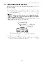
Страница 162: ...one hand and carefully lower it on top of the tribrach while at the same time coinciding the alignment piece with the tribrach alignment groove on the instrument and tribrach respectively 2 When full...

Страница 163: ...is turned on V ANGLE Z0 H0 ZENITH 0 HORIZONTAL 0 Choose the vertical angle reading from zenith or from level N TIMES REPEAT N TIMES REPEAT Select the measurement mode for distance when the power is t...

Страница 164: ...Select REC A or REC B for data output REC A The measurement is made again and this new data is output REC B The data being displayed is output CR LF ON OFF It is possible to output the data with carr...

Страница 165: ...et menu F1 F4 7 Press ESC key Returns to PARAMETERS 2 menu ESC 8 Press F3 OTHERS SET key F3 9 Press F4 P key to get the function in page 2 F4 MENU 3 4 F1 ILLUMINATION F2 PARAMETERS 1 F3 PARAMETERS 2 P...

Страница 166: ...17 4 17 SELECTING MODE 10 Press F1 key F1 11 Press F1 ON key and press F4 ENTER key Returns to OTHERS SET menu F1 F4 NEZ MEMORY OFF ON OFF ENTER OTHERS SET 2 5 F1 NEZ MEMORY F2 REC TYPE F3 CR LF P...

Страница 167: ...adjusting 1 Level while checking the display see Section 2 5 2 Levelling If the tilt sensor is misaligned the circular level is not adjusted correctly 2 Check the position of the bubble of the circul...

Страница 168: ...lay 1 Level the instrument properly with the plate level 2 While pressing the F1 key turn power switch ON F1 Power ON 3 Press the F1 key F1 4 Collimate target A from the telescope properly in normal s...

Страница 169: ...ON 3 Press the F2 key F2 4 Press the F1 key F1 5 Collimate target A FACE 1 Collimate A Normal 6 Press the F4 SET key 1 The sample display shows that the measurement is made 5 times in FACE 1 F4 7 Turn...

Страница 170: ...get the average value from 1 to 10 measurements To get the average repeat the procedures in steps 5 6 or 10 11 The measured times is counted in the second line of display 2 The compensation values of...

Страница 171: ...ine positions Perform check in weak sunlight and no scintillation Tilt crn should be se to Yes H V and coll crn to Yes in Obs condition while performing checks 1 Carefully level the instrument 2 Insta...

Страница 172: ...ptical Plummet Checking 1 Carefully level the ES and exactly center a survey point in the reticle of the optical plummet 2 Turn the upper part 180 and check the position of the survey point in the ret...

Страница 173: ...d to 0 before delivery Although it almost never deviates use a baseline with a known distance precision to check that the additive distance constant K is close to 0 several times a year and whenever t...

Страница 174: ...erformed using an adjustment target cut out and use targets printed at the back of this manual As this target is made of paper great care must be taken to prevent it getting wet Checking 1 Level the i...

Страница 175: ...d hexagon key wrench into both the upper and lower screws b Slightly loosen the upper lower screw and tighten the lower upper screw Make sure that the tightening tension for both screws is identical C...

Страница 176: ...he fine adjustment screws moves the laser plummet beam in the directions shown below Up Right Left Down Tighten Up screw Tighten Right screw Tighten Down screw Tighten Left screw Fine adjustment screw...

Страница 177: ...ress ENT key to create a new job If there is another job with the same name the existing job will be selected A maximum of 15 job files can be registered ENT MENU 1 4 F1 TOP FIELD F2 DATA COLLECT F3 L...

Страница 178: ...name will be displayed at the top right of TOP FIELD of the main menu Operating procedure Operation Display 1 Select F1 TOP FIELD from the menu MENU F1 2 Select F1 JOB 3 Select F4 to move to the secon...

Страница 179: ...enu MENU F1 2 Select F1 JOB F1 3 Job selection will be cancelled when F3 NO JOB FILE is selected F3 Operating procedure Operation Display 1 Select F1 TOP FIELD from the menu MENU F1 2 Select F2 SETTIN...

Страница 180: ...play sequence of coordinates F1 N E Z Display N E Z F2 E N Z Display E N Z F3 X Y Z Display X Y Z Select F1 F3 6 Select F1 F3 to set the distance measurement mode F1 FINE FINE mode F2 CRS 1mm COARSE m...

Страница 181: ...etting ENT Operating procedure Operation Display 1 Select F1 INST SETUP F1 2 Select F2 CREATE INST PT F2 3 Enter the coordinate point of a occupied point and its description Enter PT Enter DESC 4 Set...

Страница 182: ...nter an instrument height Enter instrument height 4 Set with ENT key ENT 5 Enter point number to collimate Collimate point number 2 to 7 points Enter colli mate point number 6 Set with ENT ENT N 0 000...

Страница 183: ...pied point coordinates will be calculated and the standard deviation will be displayed 13 Press F1 OK The screen for inputting the coordinate point of an occupied point and its description will be dis...

Страница 184: ...s press OK under the condition in which the previous prism backsight collimated F1 Operating procedure Operation Display 1 To check the collimate point coordinates during prism collimation select F2 C...

Страница 185: ...eviation with missing line distance calculated from coordinate data select F1 MEAS ANG DIST and to set up only the angle select F2 MEAS ANG ONLY For example select F1 7 Select F1 MSR The distance to c...

Страница 186: ...ate point coordinates N E Z Enter colli mate point coordiante 6 Set with ENT key ENT 7 Enter a reflector height Enter reflector height 8 Set with ENT key ENT 9 From here to the backsight setting follo...

Страница 187: ...reflector height 6 Set with ENT key ENT 7 Collimate the reflector and press F1 MSR key to begin measurement F1 8 After measuring the reflector record the coordinate data to complete the setting Opera...

Страница 188: ...essing F1 0SET will enter 0 Enter backsight 3 Set with ENT key ENT 4 Collimate the reflector and press F3 YES Set backsight to end F3 ENTER BS ANGLE BS AN _ DDD MMSS 0SET CLR ENTER BS ANGLE BS AN 0 00...

Страница 189: ...easurement and it will also display the distance difference Data is updated each time MSR is performed F1 7 Pressing F2 R L key will display distance difference in the horizontal direction instead of...

Страница 190: ...ion to record 1 Enter PT Enter DESC 3 Set with ENT key 2 ENT 4 To record the coordinate data without checking measured data select F1 FAST key F1 5 The measured coordinate data will be recorded and th...

Страница 191: ...limate point record REC them without moving the angle after measurement MSR F4 1 To change the reflector height select F2 HR key to switch to the screen for reflector height input 2 To edit a coordina...

Страница 192: ...ocedure Operation Display Select F1 ADD POINT Coordinates can be added through the following procedure 1 COORDINATES 2 REFLINE 3 TAPE F1 Operating procedure Operation Display 1 Select F1 COORDINATES F...

Страница 193: ...REFLINE F2 2 To acquire coordinate data for reference REF1 select an existing coordinate point with F1 or F2 Arrow key or enter a coordinate point directly Enter Select PT 3 Set with ENT key ENT N 0...

Страница 194: ...ow the switching of the REF1 REF2 display and DISTANCE OFFSET display F4 10 Press F1 OK to calculate coordinate data After the coordinate data is calculated the procedure will move onto coordinate poi...

Страница 195: ...r Select PT 3 Set with ENT key ENT 4 In order to acquire coordinate data for reference END point select an existing coordinate point with F1 or F2 Arrow key or enter a coordinate point directly Enter...

Страница 196: ...Enter PT Enter DESC The calculated value will be displayed for the coordinate data Set with ENT key ENT ENT Operating procedure Operation Display 1 Select F2 DELETE POINT F2 2 Select the type of data...

Страница 197: ...directly and recorded for addition of coordinates F2 MEASUREMENT PT Coordinate data observed and recorded through layout TOPO etc F1 or F2 3 Select a coordinate point to view with F1 or F2 Arrow key E...

Страница 198: ...o the editing mode by pressing F3 Edit key F3 4 After editing the coordinate point and its description set with ENT key Edit data ENT Coordinate data can be edited with the editing mode in the same ma...

Страница 199: ...NE WAY Setting Protocol ACK NAK or ONE WAY communication Baud rate 1200 2400 4800 9600 19200 38400 Setting transfer speed 1200 2400 4800 9600 19200 38400 baud Char Parity 7 EVEN 7 ODD 8 NON Setting da...

Страница 200: ...ration Display 1 Select the transmission format used for receiving data F1 GTS FORMAT F2 SSS FORMAT F1 or F2 2 Select F1 SEND DATA F1 3 Press F3 YES to begin the coordinate data sending process F3 DAT...

Страница 201: ...place the case horizontally then open the case 8 When returning the instrument to its case be sure to match the white positioning marks provided with the case and fit it correctly into the concave sh...

Страница 202: ...magnetic north After use tighten the clamp and remove the compass from the slot The tubular compass is susceptible to the influence of nearby magnets or metal Such influence could cause it to fail to...

Страница 203: ...g case to shoulder the case Interface cable Connect between the ES and the host computer for data output By using the Y cable the ES can perform RS232C communication D sub 9 pin at the same time as co...

Страница 204: ...efore operating Never use any combination other than those indicated below If you do the ES could be damaged Those indicated by are standard accessories Dedicated power cables differ according to the...

Страница 205: ...the instruments To adjust the height of prism set change the position of fixing screws During a traverse observavtion it is recommended to use the same type tribrach TR 102 103 112 of tribrach for the...

Страница 206: ...data input Confirm the input data DELETE ERROR When deleting coordinate data it can not be done successful Confirm the data and delete again SIGNAL OFF Measuring conditions are poor and there is not e...

Страница 207: ...PT EXIST Same new point name is already memorized in the memory Confirm the new point name and input again PT DOES NOT EXIST When you enter incorrect name or PT does not exist in the internal memory E...

Страница 208: ...rmful interference in which case the user will be required to correct the interference at his own expense Means of conformity This device complies with part 15 of the FCC Rules Operation is subject to...

Страница 209: ...to the following two conditions 1 this device may not cause interference and 2 this device must accept any interference including interference that may cause undesired operation of this device This eq...

Страница 210: ...e treated as household waste By ensuring this product is disposed of correctly you will help prevent potential negative consequences for the environment and human health which could otherwise be cause...

Страница 211: ...lectable Tilt angle compensation Type Liquid 2 axis tilt sensor Minimum display 1 Range of compensation 6 0 1111 gon Automatic compensator ON V H V OFF selectable Compensation constant Can be changed...

Страница 212: ...ne measurement single repeat average Rapid measurement single repeat Tracking selectable Measuring time Fine measurement 1 7 sec every 0 9 sec Rapid measurement 1 4 sec every 0 7 sec Tracking measurem...

Страница 213: ...uthentication Yes No selectable 8 Bluetooth function may not be built in depending on telecommunications regulations of the country or the area where the instrument is purchased Contact your local dea...

Страница 214: ...Signal source Red laser diode 635 10nm Class 2 IEC60825 1 Ed 3 0 2014 FDA CDRH 21CFR Part 1040 10 and 1040 11 Complies with FDA performance standards for laser products except for deviations pursuant...

Страница 215: ...t 5mm T arget for Laser plummet adjustment 5mm T arget for Laser plummet adjustment 5mm T arget for Laser plummet adjustment 5mm T arget for Laser plummet adjustment 5mm T arget for Laser plummet adju...

Страница 216: ...http www topcon co jp GLOBAL GATEWAY http global topcon com Please see the attached address list or the following website for contact addresses 2016 TOPCON CORPORATION ALL RIGHTS RESERVED...

Отзывы: