background image


59 

Chapter 6 Communication Interface 

6.1


RS232 Interface 

6.1.1


Description 

At  present,  the  widely  used  serial  communication  standard  is  the  RS-232  standard,  it  can  also  be  called  the 
asynchronous serial communication standard, it is used to implement data communication between computers 
and  computers,  between  computers  and  peripherals.  RS  is  the  English  abbreviation  of  “Recommended 
Standard”  232  is  the  standard  number.  This  standard  is  officially  published  by  the  Electronic  Industries 
Association (EIA) in 1969, it specifies that one bit of data is transmitted over a single data line at a time. Most 
serial port configurations are usually not strictly based on the RS-232 standard; Use 25-pin connector on each 
port (IMB AT uses 9-pin connector). The most common RS-232 signals are shown in the table below. 

Table 6-1 RS-232 Signal Table 


Like most serial ports in the world, the serial interface of this tester is not strictly based on the RS-232 standard, 
but only provides a minimal subset. As shown in the following table: 

Signal 

Symbol 

Connector Pin# 

Transmit Data 

TXD 

Receive Data 

RXD 

Grounding 

GND 

Table 6-2 RS-232 Signal Subset Table 


This is the easiest and the most cost effective way to use serial ports communication. The RS232C connector of 
this tester uses a 9-core pin type DB socket, and the pin sequence is shown in figure 6-1 below:


Signal 

Symbol 

25-core  connector  pin 
#   

9-core connector pin# 

Request to Send 

RTS 

Clear to Send 

CTS 

Data Set Ready 

DSR 

Data Carrier Detect 

DCD 

Data Terminal Ready 

DTR 

20 

Transmit Data 

TXD 

Receive Data 

RXD 

Grounding 

GND 

Содержание TH7105

Страница 1: ...Operation Manual TH7105 7110 7120 Programmable AC Power Source V1 0 6 2019 6 Tonghui Electronic Co Ltd www tonghui com cn...

Страница 2: ...tions 4 Chapter 2 Introduction 5 2 1 Introduction to Front Panel 5 2 2 Introduction to Rear Panel 5 2 3 Display Zoon 6 2 4 Basic Operation 7 2 4 1 Manual mode 7 2 4 1 Programmable Mode 8 2 5 Boot Inst...

Страница 3: ...troduction 47 5 2 Programmable Mode Output Function 48 5 3 Surge Drop Function 50 5 4 Dimmer Mode Function 52 5 5 Result Display Function 53 5 6 Protection Function 55 5 7 Remote Signal Output Functio...

Страница 4: ...ad Commands 131 Chapter 7 Technical Specifications 166 7 1 Product Specifications 166 7 1 1 AC Input 166 7 1 2 AC Output 166 7 1 3 Setup 166 7 1 4 Measurement 167 7 1 5 Convention 167 7 1 6 Dimension...

Страница 5: ...rument Introductions to the improvements of the instrument in performance function internal structure outer appearance accessories packing material etc are subject to change without notice If you find...

Страница 6: ...sly Starting phase angle 0 359 ending phase angle 0 359 Support surge drop and dimming mode function Support front and rear panel output Memory capacity Manual mode 50 sets Programmable mode 50 sets 9...

Страница 7: ...be used indoors and in low condensation areas The general environmental requirements of this instrument are shown in table 1 2 The fan speed changes intelligently with the radiator temperature When t...

Страница 8: ...ements 9 Keep the instrument well ventilated to avoid overheating Do not block the ventilation hole of the equipment to avoid internal temperature rising affecting the accuracy 10 Please use dry cloth...

Страница 9: ...year in which the design was approved This device complies with the marking requirements of WEEE directive 2002 96 EC and this additional product label states that this appliance electronic product s...

Страница 10: ...n labeled function keys 5 DISP Quickly switch to measurement display page 6 SETUP Quickly switch to measurement setting page 7 SYSTEM Quickly switch to system setting page 8 V SET Voltage setting 9 I...

Страница 11: ...es and choose to execute memory groups M1 M2 to M7 5 USB COM Interface Through this port TH7100 series instrument can be controlled by external controller and realize online communication with compute...

Страница 12: ...3 indicates the output power value and the parameter display 4 indicates the peak current value 5 Soft key zone This area is used to display the function menu corresponding to the cursor area 2 4 Bas...

Страница 13: ...ps 5 Test output Press the DISP button then press the ON OFF button to output 2 5 Boot Instructions Press the power switch in the lower left corner of the front panel of the instrument to turn the ins...

Страница 14: ...9...

Страница 15: ...l mode page Description and operation of setting parameters under Programmable mode page Description and operation of parameters under System setting page Description and operation under Internal file...

Страница 16: ...e via the front panel numeric keys then press ENTER or OK to confirm When changing the value with the numeric keys if you do not want to change the parameter value or press the wrong numeric key you c...

Страница 17: ...ameter cannot be changed under the programmable mode measurement display page 2 Operation Press the key or knob to move the cursor to this parameter option change the value via the front panel numeric...

Страница 18: ...y 3 1 1 2 Soft keypad description and operation Parameter Display PARA DISP 1 Description This softkey is used to switch the output parameter display As shown in Figure 3 3 Figure 3 3 2 Operation Unde...

Страница 19: ...ption This soft key is used to configure the parameters required for MESA4 press this soft key to select the power PWR peak current APK power factor PF crest factor CF Please refer to figure 3 5 Figur...

Страница 20: ...of 0 300V 2 Operation In Measurement Display page press AUTO soft key to switch between AUTO and HIGH 3 1 1 3 State Zoon Description OFF Output is not enabled AUTO Voltage mode is in AUTO Surge drop f...

Страница 21: ...ay of output parameters AUTO 1 Description This key is the voltage mode setting key which can be set to AUTO or HIGH When the voltage mode is set to AUTO it will automatically judge whether the voltag...

Страница 22: ...he icon turns green when the instrument is testing It indicates the testing time If the time is set the time will countdown and when it reaches 00 00 00 the output will be disabled automatically 3 2 M...

Страница 23: ...the key or knob to move the cursor to this parameter option change the value by front panel numeric keys then press ENTER or OK button to confirm When changing the value with the numeric keys if you d...

Страница 24: ...e is not greater than 150V the range is 0 000 8 400A When the setting voltage is greater than 150V the setting range is 0 000 4 200A When the PLC ONoff is turned on which is accessed from SysSetup the...

Страница 25: ...on 2 Operation Make use of key or the knob to move the cursor to this parameter option change the value via the front panel numeric keys then press ENTER or OK to confirm If you do not want to change...

Страница 26: ...he key or the knob to move the cursor to this parameter option then change it through the front panel numeric keys then press ENTER or OK to confirm the change If you do not want to change the paramet...

Страница 27: ...ter value or press the wrong numeric key you can cancel it by pressing the key or ESC key On PHS 1 Description This parameter is used to set the staring phase angle of output waveform Its range is 0 3...

Страница 28: ...Volt SD Site SD Time SD Cont When this parameter is set to OFF these parameters are not displayed For details please refer to Surge Drop function 2 Operation Make use of the key or the knob to move t...

Страница 29: ...ou can cancel it by pressing the key or ESC key VoltLiLmt 1 Description This parameter is used to set the output voltage limit protection This parameter is the absolute value of the difference between...

Страница 30: ...25 Figure 3 10 Sequence setting page 1 in programmable mode Figure 3 11 Sequence setting page 2 in programmable mode Figure 3 12 Sequence setting page 3 in programmable mode...

Страница 31: ...eter is set to 000 it will keep testing until the user presses ON OFF button or run into errors when it is set to 1 999 it indicates the number of cycles of the current memory setting See the programm...

Страница 32: ...change If you do not want to change the parameter value or press the wrong numeric key when changing with the numeric keys you can cancel it by pressing the key or ESC key V Mode 1 Description This pa...

Страница 33: ...g with the numeric keys you can cancel it by pressing the key or ESC key FREQ 1 Description This parameter is used to set the output frequency The range is 45 0 500Hz When the frequency is less than 1...

Страница 34: ...knob to move the cursor to this parameter option then change it with the front panel numeric keys and finish with ENTER or OK keys to confirm the change If you do not want to change the parameter val...

Страница 35: ...is parameter is set to 0 000 it means that this function is off 2 Operation Make use of the key or the knob to move the cursor to this parameter option then change it with the front panel numeric keys...

Страница 36: ...ric keys and finish with ENTER or OK keys to confirm the change If you do not want to change the parameter value or press the wrong numeric key when changing with the numeric keys you can cancel it by...

Страница 37: ...etup COMMON page is turned on When the SD Cont is turned on the range is 0 20ms When SD Cont is turned off the range is 0 99ms For details please refer to Surge Drop function instruction 2 Operation M...

Страница 38: ...e is turned on For details please refer to Surge Drop function instruction Operation Make use of key or the knob to move the cursor to this parameter option then the soft key zoon will display the cor...

Страница 39: ...en changing with the numeric keys you can cancel it by pressing the key or ESC key F HiLmt 1 Description This parameter is used to set the upper limit of the output frequency which ranges from 45 0 to...

Страница 40: ...and P F When set to LAST the display will show the final test result after the test is over When set to ALL the display will show all test results after the test is over When set to P F the display w...

Страница 41: ...s turned on Set to 000 indicating continuous loop output of current memory sequence Set to 001 999 indicating the memory sequence will be cycled several times based on your setting See program setting...

Страница 42: ...the system environment interface under SysSetup page by default If you are not on this page make use of button or the knob to move the cursor to the menu bar and then switch to this page 3 4 1 2 Setti...

Страница 43: ...Description This parameter is used to set the sound when the instrument fails the test 2 Operation Make use of the key or the knob to move the cursor to this parameter option the soft key area display...

Страница 44: ...arameter is used to set the time of the system 2 Operation Make use of the key or the knob to move the cursor to this parameter option then change it with the front panel numeric keys and finish with...

Страница 45: ...function menu of this parameter This parameter can be changed with soft keys Bus Proto 1 Description This parameter is used to set the protocol of the instrument RS232 communication interface This par...

Страница 46: ...the knob to move the cursor to this parameter option the soft key area displays the function menu of this parameter This parameter can be changed with soft keys 3 4 3 System Tool 3 4 3 1 Description a...

Страница 47: ...to move the cursor to this parameter option the soft key area displays the function menu of this parameter This parameter can be changed with soft keys Setup Reset 1 Description This parameter is used...

Страница 48: ...ternal File 4 1 2 Operation Press the SYSTEM button then press INTER FILE soft key to enter InterFile interface This instrument can operate on 54 internal files When the cursor is not in the title bar...

Страница 49: ...re the cursor is located to the U disk If no U disk is plugged in the instrument an error shall be prompt In order to operate correctly please insert a U disk into the front panel USB interface before...

Страница 50: ...nt In order to efficiently save the instrument data to the USB flash drive it is recommended not to have too many files or folders in the USB flash drive The file format and its use are described in t...

Страница 51: ...f the entered file name is the same as the previous file name a prompt will appear in the prompt bar at the bottom of the screen If a user did not enter a file name and pressed ENTER or OK the default...

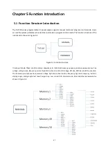
Страница 52: ...igure 5 1 Figure 5 1 Function Structure In manual mode there are 50 memory sequences in total Each memory sequence includes parameters such as voltage voltage mode frequency current high limit current...

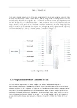
Страница 53: ...e step cycle and other parameters As shown in Figure 5 3 Figure 5 3 programmable Mode 5 2 Programmable Mode Output Function The TH7100 series programmable AC power supply can set different parameters...

Страница 54: ...1 5 M1 5 M1 5 M1 6 M1 1 M1 1 M1 2 M1 3 M1 3 M1 4 M1 4 M1 5 M1 5 M1 5 M1 6 when the LoopCycle is set to 2 MemoryCycle of memory M1 is set to 2 M1 1 Connect ON StepCycle 2 M1 2 Connect ON StepCycle 1 M1...

Страница 55: ...ge of the surge drop which ranges from 0 0 to 300V When this parameter value is greater than the set voltage it is a surge when it is less than the set voltage it is a drop This parameter is displayed...

Страница 56: ...e Drop option in ProgramSetup COMMON page is turned on Assume that the output voltage is 100V the output frequency is 50Hz the SD voltage is 60V the SD site is 25ms and the SD time is 1ms If the SD Co...

Страница 57: ...abled by default In this mode the manual mode MEMORY setting can only set parameters such as voltage frequency 45 100Hz and SD voltage The measurement display page cannot display the measurement resul...

Страница 58: ...ult display functions which are NONE LAST ALL and P F When set to NONE the screen will not display the test results after the test is completed As shown in figure 5 8 Figure 5 8 The test result is NON...

Страница 59: ...shown in figure 5 10 Figure 5 10 The test result is ALL display When set to P F PASS or FAIL will be displayed after the test is finished The output result of the test is judged based on high low limi...

Страница 60: ...t are not within range as shown in figure 5 12 Figure 5 12 The test result is P F showing FAIL 5 6 Protection Function TH7100 series programmable AC power supply provides the following protection HI A...

Страница 61: ...eds 110 of the rated full load power the display will show OPP alarm beep when the beep is on the ON OFF button indicator flashes OTP When the temperature of the heat sink of the instrument exceeds 60...

Страница 62: ...SIGNAL IN terminal is available on the rear panel of the TH7100 series programmable AC power supply After PLC Onoff of SysCom under SysSetup page is set to ON connect the remote control device to imp...

Страница 63: ...d PIN5 PROGRAM Mode M1 The control switch is connected between PIN8 and PIN5 M2 The control switch is connected between PIN9 and PIN5 M3 The control switch is connected between PIN8 PIN9 and PIN5 M4 T...

Страница 64: ...ector on each port IMB AT uses 9 pin connector The most common RS 232 signals are shown in the table below Table 6 1 RS 232 Signal Table Like most serial ports in the world the serial interface of thi...

Страница 65: ...Computer The pin definition of this tester is the same as that of the 9 core connector serial interface pin used by the IMB AT compatible machine Figure 6 2 shows the RS232 interface Figure 6 2 RS232...

Страница 66: ...232 interface is no longer the standard configuration of the PC and the USB interface is gradually being used more and more widely The USB interface of the TH7100 series programmable AC power supply c...

Страница 67: ...root thus forming a subsystem The following is part of the DISPlay subsystem to illustrate the tree system DISPlay PAGE MEAS DISPlay is a root level keyword PAGE is a second level keyword and MEAS is...

Страница 68: ...t Thus the above command can be sent in the following two ways RANGe n or RANGe UPPer n Note Do not use square brackets when using optional commands 2 Use angle brackets to indicate a argument type An...

Страница 69: ...acter A backspace followed by a NL is also possible Command string termination always resets the current SCPI command path to the root level 6 3 2 3 Command Abbreviation Rules 1 Use below rules to det...

Страница 70: ...ble register The return value is from 0 to 255 3 ESR This command can be used to read the value of the standard event register After the command is executed the value of the standard event register is...

Страница 71: ...page to the measurement display page 2 Command Syntax DISPlay PAGE MANUal MEMory Shorthand for the command DISP PAGE MANU MEM Command description Set the display page to the sequence setting page in m...

Страница 72: ...t the display page to Internal File page 6 Command Syntax DISPlay PAGE EXTerFile Shorthand for the command DISP PAGE EXTF Command description Set the display page to External File page Query Syntax DI...

Страница 73: ...ntax FUNCtion OUTPut ON or FUNCtion OUTPut 1 Shorthand for command FUNC OUTP ON or FUNC OUTP 1 Command description This command is used to turn on the AC output this command is only valid under the me...

Страница 74: ...ammable mode The command is invalid when the output is turned on Command Syntax FUNCtion RunMode Shorthand for command FUNC RM Command description This command is used to query the current test mode T...

Страница 75: ...description This command is used to query the number of cycles of the current memory sequence in the programmable mode Returns value with a value equal to 0 999 6 3 5 4 FUNC STEP Command Syntax FUNCt...

Страница 76: ...en the output is turned on Command Syntax FUNCtion VOLTage PROGram Shorthand for command FUNC VOLT PROG Command description This command is used to query the set voltage value of the current step in t...

Страница 77: ...low limit value in programmable mode value indicates the low voltage limit value and the range is 0 0 300 0V The command is invalid when the output is turned on Command Syntax FUNCtion VOLTage LOwLiM...

Страница 78: ...mode and value indicates the current high limit value When the set voltage is not greater than 150V the setting range is 0 000 8 400A when the set voltage is greater than 150V the setting range is 0...

Страница 79: ...urrent step in the programmable mode and value indicates the current low limit value When the set voltage is not greater than 150V the setting range is 0 000 8 400A when the set voltage is greater tha...

Страница 80: ...mit of the output frequency Its setting range is 45 0 500Hz When the frequency is less than 100 Hz the resolution is 0 1 Hz when the frequency is not less than 100 Hz the resolution is 1 Hz Command Sy...

Страница 81: ...etting range is 45 0 500Hz When the frequency is less than 100 Hz the resolution is 0 1 Hz when the frequency is not less than 100 Hz the resolution is 1 Hz The command is invalid when the output is t...

Страница 82: ...h limit of the current step in the programmable mode and returns value which is equal to 0 0 33 6 6 3 5 16 FUNC AP LOLMT Command Syntax FUNCtion AmperePeak LOwLiMiT value Shorthand for command FUNC AP...

Страница 83: ...000W The command is invalid when the output is turned on Command Syntax FUNCtion POWer LOwLiMiT Shorthand for command FUNC POW LOLMT Command description This command is used to query the power low lim...

Страница 84: ...n the programmable mode value indicates the delay determination time When the unit is second the range is 0 1 999 9s when the unit is minute the range is 0 1 999 9m when the unit is time the range is...

Страница 85: ...p time of the current step in the programmable mode Returns value with a value of 0 0 999 9s The command is invalid when the output is turned on Command Syntax FUNCtion RAMP DOWN value Shorthand for c...

Страница 86: ...used to query the value of the timer in manual mode It returns value and its value is equal to 0 99 Command Syntax FUNCtion TIME UNIT SECond Shorthand for command FUNC TIME UNIT SEC Command descripti...

Страница 87: ...the surge drop at the current step in the programmable mode The command is invalid when the output is turned on Command Syntax FUNCtion SurgeDrop PROGram OFF or FUNCtion SurgeDrop PROGram 0 Shorthand...

Страница 88: ...e drop in manual mode Returns value with a value equal to 0 20 Command Syntax FUNCtion SurgeDrop SITE PROGram value Shorthand for command FUNC SD SITE PROG value Command description This command is us...

Страница 89: ...hand for command FUNC SD CT MANU OFF or FUNC SD CT MANU 0 Command description This command is used to turn off the SD connection of the current memory sequence The command is invalid when the output i...

Страница 90: ...et the starting angle of the current step in the programmable mode value indicates the starting angle and the range is 0 359 The command is invalid when the output is turned on Command Syntax FUNCtion...

Страница 91: ...MANU ALL or FUNC RESULT MANU 2 Command description This command is used to set the result display mode to ALL in manual mode Command Syntax FUNCtion RESULT MANUal P F or FUNCtion RESULT MANUal 3 Short...

Страница 92: ...ription This command is used to exit the result display state The command is invalid when the output is turned on 6 3 5 30 FUNC SR Command Syntax FUNCtion SaveResult Shorthand for command FUNC SR Comm...

Страница 93: ...e Command is invalid when output is turned on Command Syntax FUNCtion OverCurrentFold PROGram Shorthand for command FUNC OCF PROG Command description This command is used to query the state of over cu...

Страница 94: ...the programmable mode Returns 1 when the single step test function is turned on and 0 when the single step test function is turned off 6 3 5 35 FUNC VOLT LMT Command Syntax FUNCtion VOLTage LilMT valu...

Страница 95: ...mmand is used to query the output current value in manual mode and the command is valid when the output is turned on 6 3 6 3 FETCH POW Command Syntax FETCH FETCH FETCH POWer Shorthand for command FETC...

Страница 96: ...ed to query the crest factor value in manual mode and the command is valid when the output is turned on 6 3 6 7 FETCH Command Syntax FETCH Command description This command is used to query the measure...

Страница 97: ...SS OFF or SYSTem BEEP PASS 0 Shorthand for command SYST BEEP PASS OFF or SYST BEEP PASS 0 Command description This command is used to turn off the pass beep Command Syntax SYSTem BEEP PASS Shorthand f...

Страница 98: ...Y Command description This command is used to query the status of the beep key Command Syntax SYSTem BEEP ALARM ON or SYSTem BEEP ALARM 1 Shorthand for command SYST BEEP ALARM ON or SYST BEEP ALARM 1...

Страница 99: ...is from 1 to 12 Command Syntax SYSTem DATE value Shorthand for command SYST DATE value Command description This command is used to set the system date value can be from 1 to 31 Command Syntax SYSTem D...

Страница 100: ...used to query the second of the system time Returns value it is 0 59 6 3 7 4 SYST PLC Command Syntax SYSTem PLC ON or SYSTem PLC 1 Shorthand for command SYST PLC ON or SYST PLC 1 Command description...

Страница 101: ...to internal storage name indicates the name of the file to save When the saved file name has the same name as the internally stored file the system cannot save it Users can check whether the file name...

Страница 102: ...rmat 1 Sending Address The sending address refers to the local address of the instrument which can be set in the parameter bus interface of the communication setting interface of the instrument The va...

Страница 103: ...scription of Read Instruction Send Format Return Format 1 Sending Address The sending address refers to the local address of the instrument which can be set in the parameter bus interface of the commu...

Страница 104: ...ction of the instrument as shown in below table 3 Send Instruction Format Instrument address Function code High address Low address High bytes Low bytes Number of data Data byte 1 Data byte 2 CRC Low...

Страница 105: ...mode Instruction data byte 1 ranges from 1 to 50 The command is invalid when the output is turned on 2 Send Instruction Format Instrument address Function code High address Low address High bytes Low...

Страница 106: ...mode as shown in below table 2 Send Instruction Format Instrument address Function code High address Low address High bytes Low bytes Number of data Data byte 1 Data byte 2 CRC Low CRC High 1 32 0x10...

Страница 107: ...current high limit value in manual mode When the set voltage is not greater than 150V the command data range is 0 000 8 400A when the set voltage is greater than 150V the command data range is 0 000 4...

Страница 108: ...3 Return Instruction Format 6 4 2 9 Address 10 SD Voltage 1 Commands Description This command is used to set the voltage value of the surge drop set in manual mode The instruction data byte range is...

Страница 109: ...ion where the surge drop appears in manual mode Instruction data byte 1 ranges from 0 to 20 The command is invalid when the output is turned on 2 Send Instruction Format Instrument address Function co...

Страница 110: ...nstruction Format 6 4 2 13 Address 14 Voltage High Limit 1 Commands Description This command is used to set the voltage upper limit value in manual mode The command data range is 0 0 300 0V The comman...

Страница 111: ...y in manual mode When the set voltage is not greater than 150V the command data range is 45 0 500Hz When the frequency is less than 100 Hz the resolution is 0 1 Hz when the frequency is not less than...

Страница 112: ...e 1 Commands Description This command is used to set the low limit of the output frequency in manual mode When the set This command is used to set the starting angle in manual mode The command data ra...

Страница 113: ...instrument as shown in below table Data Byte Result Display Mode 0x00 This command is used to set the result display mode to NONE in manual mode 0x01 This command is used to set the result display mod...

Страница 114: ...uction Format 6 4 2 21 Address 22 Over Current Fold 1 Commands Description This command is used to control the over current fold function in manual mode The command is invalid when the output is turne...

Страница 115: ...based on the first 11 bytes 3 Return Instruction Format 6 4 2 23 Address 24 Timer Seconds 1 Commands Description This command is used to set the value of the timer seconds in manual mode Instruction d...

Страница 116: ...based on the first 9 bytes 3 Return Instruction Format 6 4 2 25 Address 26 Timer Hours 1 Commands Description This command is used to set the value of the timer hours in manual mode Instruction data...

Страница 117: ...d based on the first 8 bytes 3 Return Instruction Format 6 4 2 27 Address 28 Sequence Number 1 Command Description This command is used to set the number of cycles of the current memory sequence in th...

Страница 118: ...on the first 9 bytes 3 Return Instruction Format 6 4 2 29 Address 30 Step Number 1 Command Description This command is used to set the number of cycles for the current step in the programmed mode The...

Страница 119: ...tion Format 6 4 2 31 Address 32 Voltage Mode 1 Command Description This command is used to set the voltage output mode in manual mode Instruction data byte bit corresponds to instrument voltage output...

Страница 120: ...bytes Low bytes Number of data Data byte 1 4 CRC Low CRC High 1 32 0x10 0x00 0x21 0x00 0x02 0x04 0 000 8 400 or 0 000 4 200 4 bytes stored in float point type Calculated based on the first 11 bytes 3...

Страница 121: ...olution is 1 Hz Command is invalid when output is turned on 2 Send Instruction Format Instrument address Function code High address Low address High bytes Low bytes Number of data Data byte 1 4 CRC Lo...

Страница 122: ...to set the peak current high limit value of the current step in the programmed mode When the voltage mode is AUTO and the voltage is less than 150V the range is 0 0 33 6A when the voltage mode is AUT...

Страница 123: ...33 6 4 bytes stored in float point type Calculated based on the first 11 bytes 3 Return Instruction Format 6 4 2 38 Address 39 Power High Limit 1 Command Description This command is used to set the p...

Страница 124: ...actor of the current step in the programmed mode The command data range is 0 000 1 000 Command is invalid when output is turned on 2 Send Instruction Format Instrument address Function code High addre...

Страница 125: ...grammed mode Command is invalid when output is turned on The instruction data byte bit corresponds to the function of the instrument as shown below Data Byte Result Display Mode 0x00 This command is u...

Страница 126: ...loat point type Calculated based on the first 11 bytes 3 Return Instruction Format 6 4 2 44 Address 45 Test Time 1 Command Description This command is used to set the test time of the current step in...

Страница 127: ...float point type Calculated based on the first 11 bytes 3 Return Instruction Format 6 4 2 46 Address 47 Fall Time 1 Command Description This command is used to set the fall time of the current step i...

Страница 128: ...1 bytes 3 Return Instruction Format 6 4 2 48 Address 49 SD Position 1 Command Description This command is used to set the position where the surge drop appears in the programmed mode The command data...

Страница 129: ...ent step in the programmed mode Command is invalid when output is turned on The instruction data byte bit corresponds to the function of the instrument as shown below Data Byte Step Connection 0x00 Th...

Страница 130: ...type Calculated based on the first 11 bytes 3 Return Instruction Format 6 4 2 52 Address 53 Voltage Low Limit 1 Command Description This command is used to set the low voltage limit value in the prog...

Страница 131: ...1 32 0x10 0x00 0x36 0x00 0x02 0x04 45 0 500 0V 4 bytes stored in float point type Calculated based on the first 11 bytes 3 Return Instruction Format 6 4 2 54 Address 55 Frequency Low Limit 1 Command...

Страница 132: ...Low CRC High 1 32 0x10 0x00 0x38 0x00 0x01 0x02 0 359 High 8 bit 0 359 Low 8 bit Calculated based on the first 9 bytes 3 Return Instruction Format 6 4 2 56 Address 57 End Angle 1 Command Description T...

Страница 133: ...ALL in programmed mode 0x02 This command is used to set the result display mode to P F in programmed mode 2 Send Instruction Format Instrument address Function code High address Low address High byte...

Страница 134: ...rent Fold 1 Command Description This command is used to control the over current fold function in the programmed mode Command is invalid when output is turned on The command data byte bit corresponds...

Страница 135: ...step test function in the programmed mode Command is invalid when output is turned on The command data byte bit corresponds to the function of the instrument as shown below Data Byte Over Current Fol...

Страница 136: ...based on the first 9 bytes 3 Return Instruction Format 6 4 3 MODBUS Read Commands 6 4 3 1 Address 1 Instrument Model 1 Command Description This command is used to query the model number of the instrum...

Страница 137: ...he instrument output is on 6 4 3 3 Address 3 Test Mode 1 Command Description This command is used to query the test mode 1 32 0x03 0x00 0x01 0x00 0x01 Calculated based on the first 6 bytes Instrument...

Страница 138: ...s command is used to query the set voltage in manual mode Instrument address Function Code High Address Low Address High bytes Low bytes CRC Low CRC High 1 32 0x03 0x00 0x03 0x00 0x01 Calculated based...

Страница 139: ...sed to query the output frequency value in the current manual mode Instrument address Function Code High Address Low Address High bytes Low bytes CRC Low CRC High 1 32 0x03 0x00 0x05 0x00 0x02 Calcula...

Страница 140: ...ess 9 Current Low Limit 1 Command Description This command is used to query the current low limit value in the current manual mode Instrument address Function Code High Address Low Address High bytes...

Страница 141: ...used to query the location of the surge drop in manual mode Instrument address Function Code High Address Low Address High bytes Low bytes CRC Low CRC High 1 32 0x03 0x00 0x09 0x00 0x02 Calculated ba...

Страница 142: ...ress Function Code High Address Low Address High bytes Low bytes CRC Low CRC High 1 32 0x03 0x00 0x0B 0x00 0x01 Calculated based on the first 6 bytes Instrument address Function Code Number of Data Da...

Страница 143: ...the low limit of the voltage in manual mode 2 Send Instruction Format 1 32 0x03 0x00 0x0D 0x00 0x01 Calculated based on the first 6 bytes Instrument address Function Code Number of Data Data Byte1 Dat...

Страница 144: ...ency high limit in manual mode 2 Send Instruction Format 1 32 0x03 0x00 0x0F 0x00 0x02 Calculated based on the first 6 bytes Instrument address Function Code Number of Data Data Byte 1 4 CRC Low CRC H...

Страница 145: ...nual mode 2 Send Instruction Format 1 32 0x03 0x00 0x11 0x00 0x02 Calculated based on the first 6 bytes Instrument address Function Code Number of Data Data Byte 1 4 CRC Low CRC High 1 32 0x03 0x04 45...

Страница 146: ...rn command data is 0x03 it means that the result display mode is P F in manual mode 6 4 3 21 Address 21 Surge Drop 1 Command Description This command is used to query the state of the surge drop in ma...

Страница 147: ...and Description This command is used to query the allowable voltage difference between the set voltage and the output Instrument address Function Code High Address Low Address High bytes Low bytes CRC...

Страница 148: ...mode 2 Send Instruction Format Instrument address Function Code High Address Low Address High bytes Low bytes CRC Low CRC High 1 32 0x03 0x00 0x17 0x00 0x02 Calculated based on the first 6 bytes Inst...

Страница 149: ...nction Code High Address Low Address High bytes Low bytes CRC Low CRC High 1 32 0x03 0x00 0x19 0x00 0x01 Calculated based on the first 6 bytes Instrument address Function Code Number of Data Data Byte...

Страница 150: ...0x1B 0x00 0x01 Calculated based on the first 6 bytes Instrument address Function Code Number of Data Data Byte1 Data Byte2 CRC Low CRC High 1 32 0x03 0x02 0x00 1 50 Calculated based on the first 5 by...

Страница 151: ...t address Function Code Number of Data Data Byte1 Data Byte2 CRC Low CRC High 1 32 0x03 0x02 0x00 1 9 Calculated based on the first 5 bytes Instrument address Function Code High Address Low Address Hi...

Страница 152: ...s not greater than 150V the return command data range is 0 000 8 400A when the set voltage is greater than 150V the return command data range is 0 000 4 200A When this parameter returns to 0 000 it me...

Страница 153: ...he current step in the programmed mode 2 Send Instruction Format Instrument address Function Code Number of Data Data Byte 1 4 CRC Low CRC High 1 32 0x03 0x04 0 000 4 200 or 0 000 8 400 4 bytes stored...

Страница 154: ...ected to the open state 6 4 3 37 Address 37 AP HiLmt 1 Command Description This command is used to query the peak current high limit value of the current step in the programmed mode 2 Send Instruction...

Страница 155: ...oltage mode is HIGH the range is 0 0 16 8A When this parameter returns to 0 0 it means that this feature is off 6 4 3 39 Address 39 Power High Limit 1 Command Description This command is used to query...

Страница 156: ...factor of the current step in the programmed mode 2 Send Instruction Format Instrument address Function Code High Address Low Address High bytes Low bytes CRC Low CRC High 1 32 0x03 0x00 0x27 0x00 0x...

Страница 157: ...the time unit of the current step in the programmed mode Instrument address Function Code High Address Low Address High bytes Low bytes CRC Low CRC High 1 32 0x03 0x00 0x29 0x00 0x02 Calculated based...

Страница 158: ...at The return instruction data range is from 0 1 to 999 9 When the time unit is second the value is 0 1 999 9s when the time unit is minute the value is 0 1 999 9m when the time unit is time the value...

Страница 159: ...on Format 3 Return Instruction Format Return instruction data range is 0 1 999 9s Instrument address Function Code High Address Low Address High bytes Low bytes CRC Low CRC High 1 32 0x03 0x00 0x2D 0x...

Страница 160: ...is 0 0 300 0V Instrument address Function Code High Address Low Address High bytes Low bytes CRC Low CRC High 1 32 0x03 0x00 0x2F 0x00 0x02 Calculated based on the first 6 bytes Instrument address Fun...

Страница 161: ...at Return instruction data byte range is 0 20 Instrument address Function Code High Address Low Address High bytes Low bytes CRC Low CRC High 1 32 0x03 0x00 0x31 0x00 0x01 Calculated based on the firs...

Страница 162: ...Instruction Format The return instruction data range is 0 0 300 0V When this parameter returns to 0 0 it means that this feature is turned off Instrument address Function Code High Address Low Address...

Страница 163: ...0 1 Hz when the frequency is not less than 100 Hz the resolution is 1 Hz When this parameter returns to 0 0 it means that this feature is turned off Instrument address Function Code High Address Low...

Страница 164: ...ed mode 2 Send Instruction Format 3 Return Instruction Format Return instruction data range is 0 359 Instrument address Function Code High Address Low Address High bytes Low bytes CRC Low CRC High 1 3...

Страница 165: ...he result display mode is ALL in the programmed mode when the return command data is 0x02 it means that the result display mode is P F in the programmed mode Instrument address Function Code High Addr...

Страница 166: ...0 means that the over current is always off in the programmed mode 1 means that the over current is always on in the programmed mode Instrument address Function Code High Address Low Address High byte...

Страница 167: ...grammed mode 1 means that the single step test status is on in the programmed mode Instrument address Function Code High Address Low Address High bytes Low bytes CRC Low CRC High 1 32 0x03 0x00 0x3D 0...

Страница 168: ...is 0 000 8 400A Instrument address Function Code High Address Low Address High bytes Low bytes CRC Low CRC High 1 32 0x03 0x00 0x40 0x00 0x02 Calculated based on the first 6 bytes Instrument address F...

Страница 169: ...d the voltage is greater than 150V or the voltage mode is HIGH the return command data range is 0 0 16 8A Instrument address Function Code High Address Low Address High bytes Low bytes CRC Low CRC Hig...

Страница 170: ...000 1 000 Instrument address Function Code High Address Low Address High bytes Low bytes CRC Low CRC High 1 32 0x03 0x00 0x44 0x00 0x02 Calculated based on the first 6 bytes Instrument address Functio...

Страница 171: ...ency 45 0Hz 500Hz Maximum current RMS 0 150Vac 4 2A 8 4A 16 8A 0 300Vac 2 1A 4 2A 8 4A Maximum current AP 0 150Vac 16 8A 33 6A 67 2A 0 300Vac 8 4A 16 8A 33 6A Phase 1 2W THD When output voltage 80 140...

Страница 172: ...0Hz 500Hz Resolution 0 1Hz 45 0Hz 99 9Hz 1Hz 100Hz 500Hz Accuracy 0 1Hz Current Range 0 150Vac 0 000 4 200A 0 000 8 400A 0 000 16 800A 0 300Vac 0 000 2 100A 0 000 4 200A 0 000 8 400A Resolution 0 001A...

Страница 173: ...temperature protection OTP LCD Display 4 3 inch 480 270 Interface USB COM RS232 USBHOST Table 7 5 Convention 7 1 6 Dimension Length mm 600 602 Width mm 430 430 Height mm 88 176 Net Weight Kg 30 40 75...

Страница 174: ...ot replace the internal components of the instrument without authorization after the instrument is repaired it needs to be re calibrated to avoid affecting the test accuracy Due to the blind maintenan...

Страница 175: ...to the measurement display page DISP PAGE MANU MEM Set the display page to the sequence setting page in manual mode DISP PAGE MANU COMM Set the display page to the common settings page in manual mode...

Страница 176: ...age output in manual mode to AUTO mode FUNC VOLT MODE MANU HIG H Set the voltage output in manual mode to HIGH mode FUNC VOLT MODE MANU Query the voltage output mode in manual mode Return 0 or 1 Frequ...

Страница 177: ...U value Set the OFF phase in manual mode FUNC EANG MANU Query the OFF phase in manual mode Test Result FUNC RESULT MANU 0 Set the result display mode to NONE in manual mode FUNC RESULT MANU 1 Set the...

Страница 178: ...e current step in the programmed mode Voltage FUNC VOLT PROG value Set the voltage of the current step in the programmed mode FUNC VOLT PROG Query the voltage of the current step in the programmed mod...

Страница 179: ...ue Set the power factor high limit of the current step in the programmed mode FUNC PF HILMT Query the power factor high limit of the current step in the programmed mode PF LoLmt FUNC PF LOLMT value Se...

Страница 180: ...C SD CT PROG 0 Turn off the step connection of the memory sequence current step in program controlled mode FUNC SD CT PROG 1 Turn on the step connection of the memory sequence current step in program...

Страница 181: ...memory sequence in the programmed mode FUNC SD PROG Query the state of surge drop at the current step of the memory sequence in the programmed mode Return 0 or 1 Over Current Fold FUNC OCF PROG 0 Tur...

Страница 182: ...TIME Query the system time Hour SYST TIME HOUR value Set the hour of the system time SYST TIME HOUR Query the hour of the system time Minute SYST TIME MIN value Set the minute of the system time SYST...

Страница 183: ...5 indicates that the instrument model is TH7105 7110 indicates that the instrument model is TH7110 and 7120 indicates that the instrument model is TH7120 7110 7120 2 1 Read Write 0 Set or read the sta...

Страница 184: ...mode 19 1 Read Write 0 359 Set or query the end angle in manual mode 20 1 Read Write 0 Set or query the result display mode in manual mode 0 means the result display mode is NONE in manual mode 1 mea...

Страница 185: ...nnection is on 1 37 2 Read Write 0 4 2or0 8 4 Set or query the ampere peak high limit value in the programmed mode 38 2 Read Write 0 4 2or0 8 4 Set or query the ampere peak low limit value in the prog...

Страница 186: ...med mode 56 1 Read Write 0 359 Set or query the staring angle in the programmed mode 57 1 Read Write 0 359 Set or query the end angle in the programmed mode 58 1 Read Write 0 Set or query the result d...

Страница 187: ...d misleading with voltage mode 3 Chang Figure1 1 V1 0 2 2018 03 1 Amend FUNCtion sub system commandFigure6 7 image command error V1 0 3 2018 04 1 Amend Figure 3 9 add voltage limit parameters 2 Change...

Отзывы: