2700-4001_22 IMA Manual
18
Last Revision: 12/14/2021
4:
IMA
M
ECHANICAL
I
NSTALLATION
Before installation and commissioning of the equipment, this manual and all accompanying manufacturer
documents and manuals MUST be completely read by the appropriate personnel. All warning texts must be given
special attention.
4.1 Tolomatic IMA Actuator System Configuration
Tolomatic IMA Actuator series actuators incorporate an integral brushless servo motor. The design of the motor
with the proper feedback device allows the IMA to be powered by nearly every brand of brushless drive on the
market. This flexibility allows the IMA actuator to be used in the highest performing single and multi-axis motion
control systems. It is recommended that all servo amplifiers and drives be selected based on the following
important parameters:
a) CE and UL approved system
b) Thermal switch input
c) Drive sizing key parameters for Tolomatic IMA Actuator
i) Peak current
ii) Voltage
iii) Peak RPM
iv) Max current frequency
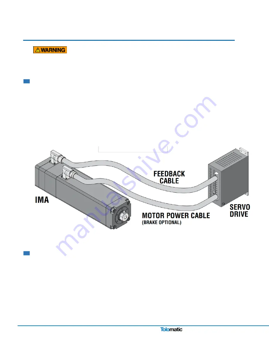
Figure 4.1: Typical connections for a single-axis system with an Tolomatic IMA Actuator with optional brake to a
RSW servo system drive
4.2 General Operation
General Operation
The IMA actuator functions by translating the rotary motion of the integral brushless servo motor into linear motion
using a screw mechanism. The linear travel, speeds and forces are controlled in conjunction with a brushless
servo drive.
When ordered the IMA actuator can be configured with any one of the following feedback devices: Digital encoder,
resolver, multi-turn absolute encoder. Please confirm you are using a version of software that supports the correct
feedback device and operation of IMA actuators.
The relationship between the rotary motion of the motor and the linear motion of the actuator corresponds to the
following relationships:


