background image

_


Doc# 16302 

Press Pilot 150 Manual 

Page 22 


5  

Configuration screens 


The PP150 is equipped with configuration screens to enhance 

certain functions and change settings according to system 
requirements. 


To put in configuration mode: 


1) 

Locate SW1 (Red 4-Dip switch) inside edge of the PP150 on 

the door. 

2)     Move dip #1 to the on position. (See Fig. 5-1) 


Fig. 5-1                             Fig. 5-2 


Note: For 

“advanced settings”

, move dip #3 to the on position as 

well.  (See Fig. 5-2) 


To cycle through the screens use the 


or  keys. 

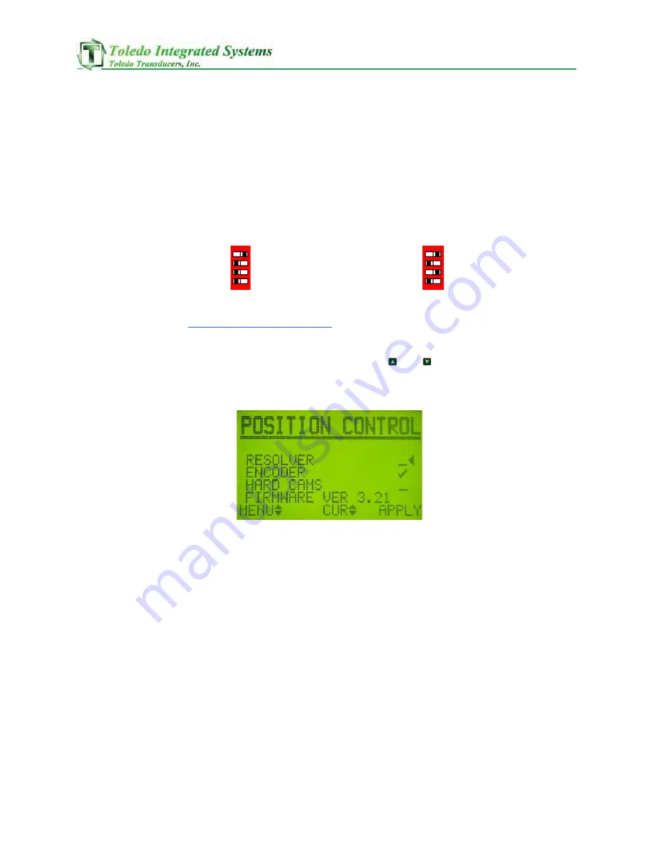
I.      POSITION CONTROL 


This screen gives the control three separate ways to track 

position. Apply Resolver to use the resolver based controls, 

Encoder for the encoder based controls, or Hard Cams for the 
Cam based controls. The PP150 is limited in its speed depending 

on what system Is chosen to run. The Resolver based system can 

run up to 1700 Strokes Per Minute. The Encoder based system 
can run up to 500 Strokes Per Minute, and the Cam based system 

can run up to 300 Strokes Per Minute.

Содержание Press Pilot 150

Страница 1: ...Toledo Integrated Systems Toledo Transducers Inc Press Pilot 150 Manual And Installation guide ...

Страница 2: ......

Страница 3: ...The express warranty set forth herein is in lieu of all other warranties expressed or implied including without limitation any warranties of merchant ability or fitness for particular purpose All such warranties are hereby disclaimed and excluded by the manufacturer Repair or replacement of defective products as provided above is the sole and exclusive remedy provided there under The manufacturer ...

Страница 4: ..._ Doc 16302 Press Pilot 150 Manual Page 2 ...

Страница 5: ... buttons 8 ii Prox Check Input 8 iii FAULT Reset Button LCD Refresh 8 iv Arm Continuous Button 8 v Mode Selector Switch 9 vi Top Stop Button 9 VII Clutch Air Switch Counterbalance Switch 10 VIII Main Motor Forward Contact 10 IX Immediate Stop Input 10 X ESR 1 and ESR 2 10 XI Resolver Encoder Inputs 11 XII Clutch Sol Valve Flt Monitor 11 XIII Bcam and Tcam 12 3 User Outputs i Clutch 1 2 14 ii Clutc...

Страница 6: ...30 xiii Led Display 30 xiv Lifetime Counter 31 xv Save Restore 31 xvi Prox setup 32 6 Troubleshooting 33 i Fault Displays and Corrective Action 33 ii Input Diagnostic Screens 42 iii Resolver wiring 44 iv Resolver Dip Switching 45 7 Start up Procedure 46 8 Start up Checklist 50 9 Configuration Settings i Configuration Datasheet 50 ii Speed Comp Top Stop Zone Settings 51 iii Board replacement parts ...

Страница 7: ... 78 17 Programmable Outputs 82 18 mute LC on upstroke with encoder setup 83 19 PP150 screen menus 100 20 Schematics 101 109 IO Wiring Pg 1 101 IO Wiring Pg 1 with Footswitch 102 IO Wiring Pg 2 103 PP150 Dimensions 104 Flush Mount Cutout 105 Flush Mount Dimensions 106 Remote LCD Cutout 107 Remote LCD Wiring 108 Remote Proface Screen Cutout Dimensions 109 21 PP150 Ethernet remote screen 110 ...

Страница 8: ...e Outputs Added PLS motion detect bit and spm to Ethernet Modified Hyd OL to include Pumping 2056 Added functionality to counters 2060 added prompt must inch 1st stroke 2061 modified t cam off to be speed comp default stop 2062 modified multiple run bar check 2063 modified auto single to unarm if t stop is push and clutch is still on 2064 added count to the remote display 2065 allow count to reset...

Страница 9: ...creen over enet counters only with screen extended clutch no motion timer 3022 modified pls save to save after they leave the pls screen 3023 modified the clutch on and no motion fault timer 3024 Modified the I O Board Replacements Parts Info 3027 Z Pulse Mute on upstroke programming 3028 Arm Auto Single Stroke bug fix 3029 Digital filter for Resolver Position 3030 Clutch engagement fix for single...

Страница 10: ...n 500ms milliseconds of an incorrect contact state on the run buttons This fault is automatically reset when an anti tie down situation is cleared II Prox Check Input The system requires a proximity switch to check position in a settable window throughout each stroke The proximity switch must be mounted separately from the resolver encoder in order to account for chain break or slippage on the pre...

Страница 11: ...ressed again in order for the ram to move a second stroke Continuous When the key is in this position the ram will cycle continuously until stopped by a Top Stop E Stop or Immediate Stop command or until a PP150 fault is detected This mode requires a Prior Action button to arm Once armed if the Run Buttons are not pressed within a settable period of time 2 10 seconds the Continuous Armed circuit w...

Страница 12: ... Stopj is available for use if more than one immediate stop device is needed Immed Stopj is not an immediate stop device input If the auxiliary immediate stop terminal block Immed Stopj is used it must be wired in series with the Immed Stop terminal block in order for the device to properly immediately stop the press X ESR 1 and ESR 2 These inputs should be wired so that two identical redundant ci...

Страница 13: ...ion II on how to calibrate the Resolver Encoder Inputs An encoder based system creates cams dependent on an automatically calculated offset and the z pulse from the encoder The PP150 has the ability to run up to 500 stokes per minute using the Encoder for press position Connect the Encoder to inputs ENC A ENC B and ENC Z Refer to the electrical schematic for wiring the encoder and Chapter 5 Sectio...

Страница 14: ...ion faults will occur during initial startup until cam switches are set in the correct sequence The PP150 can run up to 300 Strokes per Minute using a cam based system Note Shaded red areas represent closed contacts Bcam The Bcam also known as Brake Cam or Bottom Cam is used to detect a faulty flywheel brake and where the bottom of the stroke occurs Set Bcam to turn on near the top of the stroke a...

Страница 15: ...Cam is used to take over the press run function after Tcam on and stop the press at top after Tcam off Set Tcam on to overlap Bcam near the bottom of the stroke Bcam and Tcam must overlap at the bottom of the stroke Once Tcam comes on the operator will be able to release the run buttons and the PP150 will stroke the press to top in Single stroke mode or continue to stroke in Continuous mode Adjust...

Страница 16: ... run It is suggested that a green illuminated push button be used to indicate clutch ok This will give the ability to reset the clutch and verify the ok condition Wire the light through the relay contacts Okf and Oks See the electrical schematics for wiring a device to this output IV CA Relay Continuous Armed This output will energize when the continuous cycle is armed and ready When this light is...

Страница 17: ...ary message outputs There are six outputs that are 24VDC sinking outputs These outputs represent a binary value for the PP150 messaging M0 Message Bit 0 1 M1 Message Bit 1 2 M2 Message Bit 2 4 M3 Message Bit 3 8 M4 Message Bit 4 16 M5 Message Bit 5 32 ...

Страница 18: ..._ Doc 16302 Press Pilot 150 Manual Page 16 4 PRESS PILOT 150 SCREENS The pp150 screens have moved to sheet 100 ...

Страница 19: ...odes and their respective corrective actions These numbers are also output through the Binary Message Bits 0 5 in Chapter 3 Section VI The menu can be accessed by pressing either the up arrow key or the down arrow key II BRAKE MONITOR This screen shows the real time information for the brake monitor The Stop Time number indicates how long in milliseconds it took for the press to stop during the la...

Страница 20: ...ng a Brake Monitor Test IV PROX INFO This screen shows the Last On and Last Off degrees for the prox check sensor This information is helpful in setting the Prox Check window and for troubleshooting the prox check sensor See Chapter 5 Section XVI for setting the Prox check window V MOST RECENT FAULT This screen will show the operator the fault that is presently stopping the press control The curre...

Страница 21: ...w the operator the fault that had occurred two faults before the present fault state Once a new fault occurs this screen will show the fault from the Previous Fault screen See chapter 5 for fault messages and troubleshooting VIII Programmable outputs This screen will allow the operator to view and modify the output windows for both outputs The example shows the first output turning on at 170 and o...

Страница 22: ... off Last stop reason codes 0 Press Running 1 Mode Changed 2 Immediate Stop Input Off 3 Top Stop Input Off 4 Fault Present Check History 5 90 Degree Stop Test 6 Counters Done 7 E Stop Opened 8 Run Buttons Released 9 Main Motor Forward Input Off 10 Auto Run Input Off 11 Auto Enable Input Off 12 Fault Reset PB 13 Diagnostic Dip Switch Changed ...

Страница 23: ...e digits To disable the batch counter set the Batch Pre to zero or uncheck the Stop When Done setting ii BATCH LEFT As the press runs and the batch counter has been set the Batch Left will decrease If this counter should need to be cleared cursor down to it and press the button to do so This will clear the Batch Left and start the Batch count from the preset iii STOP WHEN DONE Check this setting w...

Страница 24: ...ngs move dip 3 to the on position as well See Fig 5 2 To cycle through the screens use the or keys I POSITION CONTROL This screen gives the control three separate ways to track position Apply Resolver to use the resolver based controls Encoder for the encoder based controls or Hard Cams for the Cam based controls The PP150 is limited in its speed depending on what system Is chosen to run The Resol...

Страница 25: ...n to get the resolver offset To change the resolver offset press the key The right screen is where the user sets the desired angle when using an encoder for position Stop the press at a known position enter the desired angle then put it in cal mode by checking cal mode on It will say in cal mode inch press once Inch the press one time The PP150 will come out of cal mode automatically once the enco...

Страница 26: ...ot visible when Hard Cams are chosen on the Position Control screen This screen is where the settings for arming the press in continuous are changed Arming the press in continuous can be done three different ways Anywhere means the press can be armed continuous regardless of position Top Zone means the press can only be armed in top zone Top zone is defined by the window between Tcam off and Bcam ...

Страница 27: ...ree by 1 or Use the left set of Up Down arrow keys to increase or decrease the degree by 10 VII LC MUTE TOPSTOP This screen is not visible when Hard Cams are chosen on the Position Control screen This screen lets the user select Light curtain muting and top stop settings Checking the Mute Curtains setting will mute or ignore the light curtains on the up stroke only Go to page 83 to mute light curt...

Страница 28: ... 2 Stroke Top Stop will set the press to top stop on the second stroke around This is only used in high speed applications where it will take more than 360 degrees to stop the press VIII SPEED COMP TOP 1 This screen is not visible when Hard Cams are chosen on the Position Control screen This screen shows the angle setup for the speed compensated top stop Fast Spm is the strokes per minute at which...

Страница 29: ... If the press stopped after zero degrees subtract however many degrees past zero it stopped from the current T cam off parameter and enter the new number into the T cam off angle Once the slow stop Spm and angle have been calculated go to the Speed Comp Top 1 screen and enter the slow strokes per minute into Slow SPM and the T cam off angle at slow speed into the Slow Stop parameter Setting the Fa...

Страница 30: ...sed to account for a top stop that is not perfectly linear These zones are usually only needed for faster presses that take more than one stroke to stop If you do not need this function simply put a zero in the offset for each of the zones1 4 The values on this screen are used in conjunction with the speed comp top stop calculation After the PP150 calculates the stop angle from the current running...

Страница 31: ...in press position for the duration of the Clt Engage timer Multi RBar This is a time in seconds that all active run stations must be depressed after the first station has given a valid run signal After the first run station is depressed all of the active run stations must depress their run buttons within this set time or a fault will be generated Drift Fault This is the timer for the amount in mil...

Страница 32: ... the key to start the test If the test is not performed in the allotted time that was set in section XI the test will automatically cancel and BRAKE TEST IS ON will disappear Once the brake test has been initialized the key can be pressed to cancel the test manually After the test has been started and the press is running at the Brake test speed an immediate stop signal will be generated at 90 deg...

Страница 33: ...s the lifetime stroke count since implementation of the pp150 The counter can be cleared by pressing the key This screen also lets the user choose whether they want their tub counter display to count up or to count down It also lets the user enter how many parts the tub counter should be incremented or decremented for each stroke Note the Parts per Stroke value does not change the Lifetime counter...

Страница 34: ... as correct If the angle is correct press the key Once this is done the PP150 creates a window The window created is the window in which the prox check must make every stroke This window is set 10 degrees before the angle verified and 30 degrees after the verified angle to create a total of 40 degrees To account for nuisance faults the PP150 has a built in de bounce program in which the prox can c...

Страница 35: ...then again in the on state to reset See Chapter 3 Section ix for further Assistance Message Code 2 102 TIE DOWN STN 1 RELEASE BUTTONS A tie down fault has occurred at station 1 Check to make sure the run buttons are released If the buttons are released check to make sure the correct contacts are being used on the corresponding inputs Note The left and right run buttons of any station being used mu...

Страница 36: ...in time designated since the first stations run buttons were depressed All active stations must be depressed within a set time after the first station is depressed in order for the PP150 to see a valid run signal When this message shows release the run buttons and try again making sure all active run stations are used at the same time If a run station is not being used it must be bypassed correctl...

Страница 37: ... reset button to clear the fault If the fault persists contact Toledo Integrated Systems for further assistance Message Code 14 114 CLUTCH ENGAGEMENT FAULT When a clutch on signal has been sent to the clutch valves and no motion is seen from the resolver encoder then this fault is declared Check the resolver encoder for proper wiring to see if the coupling to the press is OK for proper direction a...

Страница 38: ...this fault will occur Press the PP150 reset button to reset the fault Message Code 20 120 HYDRAULIC OL PUMPING PROMPT After a Hyd OL fault has been acknowledged and the press has been inched to the top zone the press will stop automatically and start pumping the hyd OL solenoid The output will stay on pumping depending on the settings until the hyd OL input is good for 10 continuous seconds See hy...

Страница 39: ...ngly and press the PP150 reset button to reset this fault Message Code 25 125 TOP STOP OVERRUN FAULT A Top stop is defined as a stopping point in the top zone of the stroke Top Zone is defined as the degrees between Tcam off and Bcam on Knowing this information the press must stop between Tcam off and Bcam on in order to top stop If the press stops after Bcam has turned on this is considered a top...

Страница 40: ... the top zone If the prox fails to cycle in the top zone and Bcam comes on this fault will occur Make sure the cams are set correctly and that the prox check cycles in the top zone Refer to Chapter 2 Section xiii for a graphical illustration Press the PP150 reset button to reset the fault Message Code 33 133 NO CAM OVERLAP AT BOTTOM Bcam and Tcam need to be set so that the degree Bcam turns off an...

Страница 41: ...not cycling twice at the top Adjust the prox as needed Press the PP150 reset button to reset the fault Message Code 39 139 Ethernet heartbeat fault When Ethernet is enabled a heartbeat signal is checked between the pp150 and the plc This is considered a communications error on the Ethernet network Check all Ethernet cables Message Code 40 140 Hydraulic OL Flt Reset to Ack When the Hyd OL input goe...

Страница 42: ... devices that are connected to the Top Stop and Top Stopj terminal blocks and verify they are not in a fault state Message Code 48 148 SPEED COMP CAL MODE ON This is a prompt indicating that the PP150 is in Speed Compensation Calibration mode The PP150 should only be run in Speed Comp Mode for the purpose of calibrating the speed compensation feature Failure to do so may cause damage to the press ...

Страница 43: ...gle enable input is on and the system is armed and waiting for the engage input to single stroke the press See the auto single Section 15 for a description of the process Message Code 59 159 CONT ON DEMAND ENABLED PUSH TO ARM This prompt means that the cont on demand enable input is on and the system is waiting to be armed See the cont on demand Section 15 for a description of the process Message ...

Страница 44: ...at the bottom of the screen and press the key to stop the test press the again The first two screens shown below are used to test the built in LED and LCD screens If the background for an input or output is dark it signifies that the output is good All of the diagnostic screens follow this format The next diagnostic screen is the binary output message screen The next diagnostic screen is the relay...

Страница 45: ...screens as show indicate that the N C contacts for run station 1 are on and run stations 2 3 4 are bypassed Pg 02 displays the mode of the PP150 Pg 03 displays clutch counterbalance motor clutch valve top stop and immediate stop inputs Pg 04 displays ENCODER PROX AND CAM INPUTS PG 06 DISPLAYS INPUTS 1 2 3 AND THE E STOP INPUTS The last screen tests the top three dip switch outputs on the door of t...

Страница 46: ...r In Slave Mode the PP150 does not supply excitation voltage to the resolver and is wired to the resolver input terminal of a Master device where the resolver signal is shared The resolver input consists of the following components Turns on if ROTOR voltage is too high Turns on if the 2 STATOR voltages are too high ROT STA ROT STA SW1 OFF ON SLAVE ROT STAT1 STAT2 MASTER 4 2 3 5 2 3 5 Master and Sl...

Страница 47: ...do ow wn n b bo ot th h s st ta at to or r i in np pu ut t v vo ol lt ta ag ge es s f fi ir rs st t b by y 2 2X X I If f i it t s st ti il ll l t tu ur rn ns s o on n s sc ca al le e i it t d do ow wn n f fu ur rt th he er r b by y 3 3X X a an nd d t th he en n b by y 5 5X X u un nt ti il l t th he e S ST TA AT T L LE ED D i is s n no ot t t tu ur rn ne ed d o on n P Pe er rf fo or rm m t th he e ...

Страница 48: ...f using resolver i adjust the offset angle until the press position displays the correct angle see page 22 ii Record offset on data sheet inside PP150 see page 44 b If using encoder i go to encoder cal screen ii adjust the desired angle iii enter encoder cal mode iv inch the press around until it comes out of cal mode c If using hard cams i Adjust hard cams see page 11 ii Continue to step 6 of the...

Страница 49: ...ox check has not been verified yet ii once you are sure the position is correct and the prox has cycled once go to the prox setup screen and check verify the prox position in the pp150 see page 30 iii Attempt to inch the press a full stroke if you get a fault verify the prox position again Follow this procedure until you can cycle the press completely without getting a fault Note you can view the ...

Страница 50: ...rm continuous see page 23 24 7 adjust the misc timers to the desired values see page 27 8 adjust the lc mute top stop settings to the desired values see page 24 9 adjust the brake monitor test settings see page 28 Note if you are using hard cams skip this step and proceed to step 10 ...

Страница 51: ...e counter see page 29 12 save current settings to memory to be backed up This will save all settings at their current state so in the event that a setting is modified you can restore to the initial start up settings This is done from the save restore screen in the configuration screens see page 30 ...

Страница 52: ...inch stop at top res enc only PageS 25 26 4 verify prox res enc only Page 32 5 Adjust speed comp top stop res enc only Pages 26 28 6 Adjust arm cont settings Pages 24 25 7 Adjust misc timers Page 28 8 Adjust light curtain mute and top stop settings Pages 25 26 9 Adjust brake monitor settings Run brake test Pages 29 30 10 Adjust desired led display Page 30 11 Reset lifetime counter Page 31 12 Save ...

Страница 53: ... below the values used in the Speed Comp Top Stop Zones1 4 Zone 1 If Speed SPM Stop Offset Stop Early Stop Angle Zone 2 If Speed SPM Stop Offset Stop Early Stop Angle Zone 3 If Speed SPM Stop Offset Stop Early Stop Angle Zone 4 If Speed SPM Stop Offset Stop Early Stop Angle ...

Страница 54: ..._ Doc 16302 Press Pilot 150 Manual Page 52 ...

Страница 55: ..._ Doc 16302 Press Pilot 150 Manual Page 53 ...

Страница 56: ...an Allen Bradley PLC using RSLogix 5000 1 Set the IP Address in the PP150 to the desired unused address The PP150 must be restarted before new settings become active Default is 192 168 0 254 2 Set the Subnet Mask in the PP150 to the desired value The PP150 must be restarted before new settings become active Default is 255 255 255 0 3 Settings in the PLC are explained in the next 15 pages A Open yo...

Страница 57: ...302 Press Pilot 150 Manual Page 55 C Select The communications modules and open the list by clicking on the plus symbol Figure 10 2 Figure 10 2 D Select Ethernet Module and then click ok Figure 10 3 Figure 10 3 ...

Страница 58: ...ss Pilot 150 Manual Page 56 E Enter the name you want to refer to the PP150 in your programming Sample PP150EthernetIP Figure 10 4 Figure 10 4 F Select the Comm Format to be Data INT See Sample Figure 10 5 Figure 10 5 ...

Страница 59: ... See Sample 192 168 16 146 Figure 10 6 H Enter the Assembly Instance and Size exactly as it appears in Figure 10 6 All six of these values must be entered correctly or communication will fail Figure 10 6 I Enter the correct value for the requested packet interval Figure 10 7 Figure 10 7 ...

Страница 60: ...16302 Press Pilot 150 Manual Page 58 J Right click on your MainTask Folder and select New Program Figure 10 8 Figure 10 8 K Enter the Name of the New Program as PP150 See example below Figure 10 9 Figure 10 9 ...

Страница 61: ...t 150 Manual Page 59 L Right click on the new program PP150 that you just made and select New Routine Figure 10 10 Figure 10 10 M Enter the Name of the New Routine as PP150Routine See example below Figure 10 11 Figure 10 11 ...

Страница 62: ..._ Doc 16302 Press Pilot 150 Manual Page 60 N Right click on the New Program PP150 and select Properties Figure 10 12 Figure 10 12 ...

Страница 63: ...nual Page 61 O Under the configuration tab select PP150 as the Main Routine See example below Figure 10 13 Figure 10 13 P Copy the rungs 1 9 from the sample program supplied with the PP150 See example below Figure 10 14 Figure 10 14 ...

Страница 64: ... program ladder logic Note these rungs should be copied to the PP150Routine that you just created This will ensure that the imported tags section 10 R works correctly See example below Figure 10 15 Figure 10 15 R IMPORT Program Tags by selecting Tools then Import See example below Figure 10 16 Figure 10 16 ...

Страница 65: ..._ Doc 16302 Press Pilot 150 Manual Page 63 S Select the PP150EthernetIP Tags csv file from the cd supplied with the controller See example below Figure 10 17 Figure 10 17 ...

Страница 66: ..._ Input Word 1 Figure 11 2 Doc 16302 Press Pilot 150 Manual Page 64 11 P150 Ethernet I O Mapping Figures 11 1 thru 11 8 show the mapping for all the PP150 I O Input Word 0 Figure 11 1 ...

Страница 67: ..._ Input Word 3 Figure 11 4 Doc 16302 Press Pilot 150 Manual Page 65 Input Word 2 Figure 11 3 ...

Страница 68: ..._ Doc 16302 Press Pilot 150 Manual Page 66 Input Word 4 Figure 11 5 Input Word 15 Figure 11 6 ...

Страница 69: ..._ Doc 16302 Press Pilot 150 Manual Page 67 Input Words 4 40 Figure 11 7 ...

Страница 70: ..._ Doc 16302 Press Pilot 150 Manual Page 68 Output Words 0 20 Figure 11 8 Output Word 0 Figure 11 9 Note For communication Output Word0 0 must be 1 Enabled ...

Страница 71: ..._ Doc 16302 Press Pilot 150 Manual Page 69 Output Word 1 Figure 11 10 ...

Страница 72: ...enabling plc outputs for the PP150 NOTE In the examples below Ladders 9 and 10 Figure 12 1 are required for the PP150 to monitor a heartbeat with the plc Example Ladder Logic for Required Heartbeat and Enable bits Figure 12 1 Example Ladder Logic for optional Heartbeat Monitoring Figure 12 2 Example Ladder Logic for Optional Heartbeat Fault Capture Figure 12 3 ...

Страница 73: ..._ Doc 16302 Press Pilot 150 Manual Page 71 ...

Страница 74: ...heet Installation To view the PP150 as known device in your RSLinx you must install the EDS file using the RSLinx EDS Hardware Installation Tool Figures 13 1 thru 13 7 will walk you through the installation process Run the EDS Hardware Installation Tool Program Figure 13 1 ...

Страница 75: ..._ Doc 16302 Press Pilot 150 Manual Page 73 Click on the Add button Figure 13 2 select Register a single file and Browse to search for the EDS file supplied by Toledo Integrated Systems Figure 13 3 ...

Страница 76: ..._ Doc 16302 Press Pilot 150 Manual Page 74 Click on the Next button to let Rockwell test the file Figure 13 4 Click on the Change Icon Button Figure 13 5 ...

Страница 77: ... 16302 Press Pilot 150 Manual Page 75 Click on Browse then search for the PP150 Icon ico file supplied by Toledo Integrated Systems Figure 13 6 Click on Next and the Installation will be complete Figure 13 7 ...

Страница 78: ...e made Note Enabling the Ethernet will disable some features from the PP150 screen The following features will not be able to be modified directly from the PP150 they can only be modified through the PLC using the I O Mapping see section 11 Page 54 of this manual Features that are not modifiable from the PP150 with Ethernet enabled 1 Resolver Encoder Position calibration 2 Brake Monitor Stop Limit...

Страница 79: ...q pb Selecting this option will require that the operator use the Palm Buttons to initiate the first stroke in auto mode Note The palm Buttons will operate the same as normal mode until the buttons have been held through bottom Once this occurs the unit is now armed and requires only the Initiate Auto Stroke input to engage the clutch 2 Req Off To Arm Selecting this option will require that the In...

Страница 80: ... Any Mode change v PP150 Reset Button Pushed vi Tie Down Fault Only if 1st stk req pb once through bottom this fault is bypassed vii Any Latched Fault in the PP150 viii The arm timeout timer is completed only if the clutch is off and timeout is enabled NOTE Auto Single and continuous on Demand require full press guarding by end customer Toledo Integrated Systems is not responsible for incorrect wi...

Страница 81: ...with input fault low unchecked and output hi checked If the monitored input ever turns off the output will turn off and the press will immediate stop The PP150 will report a Hydraulic OL fault and require you to push the reset button to acknowledge the fault Once the fault has been acknowledged The control will automatically tell you to inch the press either fwd or rev to the top zone If you do no...

Страница 82: ... Figures 16 3 16 6 show how the input and output settings affect the system Relays may need to be added to the output in order to integrate the system into the hydraulic overload system ex if the system has 2 valves ect Figure 16 3 Figure 16 4 ...

Страница 83: ..._ Doc 16302 Press Pilot 150 Manual Page 81 Figure 16 5 Figure 16 6 ...

Страница 84: ...output turning on at 270 and turning off at 90 typical feed window Fig 17 1 The Mo and M1 outputs share the same terminals as the message bits Only one option can be used either MSG Bits or PLS Outputs The Programmable outputs PLS must be enabled to ensure M0 and M1 cycle according to the selected windows The toggle from PLS MSG can be configured in the screen using the config advanced dip switche...

Страница 85: ...02 Press Pilot 150 Manual Page 83 18 mute light curtains on upstroke with encoder setup If the user selects mute curtains under lc mute top stop and an encoder is used the z pulse and prox must be timed as below ...

Страница 86: ......

Страница 87: ...MAIN RESOLVER ENCODER CAMS ...

Страница 88: ......

Страница 89: ......

Страница 90: ......

Страница 91: ......

Страница 92: ......

Страница 93: ......

Страница 94: ......

Страница 95: ......

Страница 96: ......

Страница 97: ......

Страница 98: ......

Страница 99: ......

Страница 100: ......

Страница 101: ......

Страница 102: ......

Страница 103: ......

Страница 104: ......

Страница 105: ......

Страница 106: ......

Страница 107: ...Doc 16302 Press Pilot 150 Manual Page 110 Toledo Integrated Systems Toledo Transducers Inc Press Pilot 150 Remote Display Manual And Installation guide ...

Страница 108: ...be a message or a fault 4 These lights will flash when communication via Ethernet is occurring 5 SPM Current strokes per minute 6 Angle The current angle of the press 7 Touch the stop history button to navigate to the stop history page See section 3 8 Touch the brake monitor button to navigate to the brake monitor page See section 4 9 Touch the counters button to navigate to the counters page See ...

Страница 109: ...SS ANGLE Figure 2 Navigate to the PRESS ANGLE screen by touching the press angle display on the HOME screen This screen shows a graphic representation of the current press angle and strokes per minute SPM Touch the HOME button to return to the HOME screen ...

Страница 110: ...gate to the FAULTS screen by touching the stop history button on the HOME screen This screen shows 1 the most recent fault 2 the previous fault 3 and two faults ago The fault number and a brief description are given Touch the HOME button to return to the HOME screen 1 2 3 ...

Страница 111: ...nitor button on the HOME screen This screen shows 1 Last stop time mS 2 Last degrees to stop Degrees 3 Max Limit for stop time mS 4 Last 90 degree test stop time mS 5 Last 90 degree test degrees to stop Degrees 6 Last 90 degree test actual speed mS 7 Current prompt fault Touch the HOME button to return to the HOME screen 1 2 3 7 4 5 6 ...

Страница 112: ...t recent reason for the clutch disengaging 2 This field displays the current PP150 prompt This prompt could be a message or a fault 3 Angle The current angle of the press 4 Stop time Last stop time mS 5 Batch count Shows the number of parts made in the batch 6 Preset Sets the number of parts per batch 7 SPM Current strokes per minute Touch the HOME button to return to the HOME screen 4 5 6 1 7 2 3...

Страница 113: ... setup button on the HOME screen Use this screen to navigate to any of the settings sub screens This screen shows 1 Pilot Press 150 input output button 2 Press Angle Settings button 3 Break Monitor Settings button 4 Programmable Limit Switch button 5 Screen Settings button Touch the HOME button to return to the HOME screen 1 2 3 4 5 ...

Страница 114: ...n There are three screens Scroll through the screens by touching the arrows All inputs and outputs are shown If the bubble next to the name of a signal is lit blue the signal is currently on These screen shows 1 Example input off 2 Example input on Touch the RETURN button to return to the SETTINGS MENU screen Figure 7 1 2 ...

Страница 115: ...Doc 16302 Press Pilot 150 Manual Page118 Figure 8 Figure 9 ...

Страница 116: ...ly be valid if activated in the pp150 This screen shows 1 Programmable Limit Switch 1 turn on angle Push to change 2 Programmable Limit Switch 1 turn off angle Push to change 3 Programmable Limit Switch 2 turn on angle Push to change 4 Programmable Limit Switch 2 turn off angle Push to change 5 Current SPM and press angle Touch the RETURN button to return to the SETTINGS MENU screen 1 2 3 4 5 ...

Страница 117: ...ngle Note touching Enter will change the angle immediately 2 If using an encoder enter current press position to change encoder angle Note touching Enter will change the angle immediately You must stroke press 1 revolution in inch mode to save encoder position 3 Enter desired angle to turn off clutch during a single stroke of top situation 0 will bypass the screen s setting and use what is in the ...

Страница 118: ... SCREEN SETUP on the settings menu Figure 6 Then enter the correct password to access this screen This screen is for use by Toledo Integrated Systems If access is required please contact Toledo Integrated Systems Touch the RETURN button to return to the SETTINGS MENU screen ...

Страница 119: ...he press needs to exceed during a 90 degree brake test 2 Press to begin 90 degree brake test This will stop the press at 90 degrees if the SPM is greater than the test speed Number 4 above 3 Max stop time mS 4 Last 90 degree test stop time mS 5 Last 90 degree test degrees to stop Degrees 6 Last 90 degree test actual speed mS 7 Current prompt fault Touch the RETURN button to return to the SETTINGS ...

Страница 120: ...3 provides the dimensions needed for the cutout in order to mount the Remote Display as well as the size of the Remote Display itself Figure 14 Figure 14 displays the method for connecting the remote display to the Press Pilot 150 including the proper designation of IP addresses ...

Отзывы: