TNA TX7232 Скачать руководство пользователя страница 5


TX7232 Base Mount Short Circuit Isolator


                          Installation & Operation Manual 


4050100390 -Rev1.0-0717 


                    TANDA UK 


Specifications are subject to change without prior notice 

5


2 Installation     


2.1 Installation Preparation 

This  interface  isolator  must  be  installed,  commissioned  and  maintained  by  a  qualified  or  factory 
trained service personnel. The installation must be installed in compliance with all local codes having 
a jurisdiction in your area or BS 5839 Part 1 and EN54. 

T&A  products  has  available  range  of  interfaces,  each  interface  isolator  is  designed  for  specific 
application,  it  is  essential  to  consider  the  requirement  of  both  sides  of  the  interface  to  avoid 
malfunction and typical fault scenario. The main caution is to ensure that the voltage rating of the 
equipment and interface isolator are compatible.   

2.2 Installation and Wiring 

1.


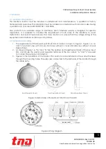
The appearance of the Base Mount Short Circuit Isolator is shown in Figure 1. Figure 1-a, 1-b 
and 1-c are front view with a cover, front view without a cover and side view without a cover, 
Respectively. 

2.


As shown in Figure 1-b, “ZI+”and “ZI-”are the positive and negative terminals of the bus input. 
ZO+ and ZO-are the positive and negative terminals of the bus output. “L+”and “L-”are used 
to connect the remote control lights. 
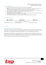
3.


Figure 2 is the installation of the isolator. The isolator can be Installed on the wall with screws 
through the mounting holes. The wires are connected to the terminals of the isolator through 
the cable entry. 


Front View(with Cover)

Front View(without Cover)

Side View(without Cover)


Figure 1 External view of Base Mount Short Circuit Isolator 


Figure 2 Wiring Diagram


Содержание TX7232

Страница 1: ...TX7232 Base Mount Short Circuit Isolator Installation and Operation Manual TANDA UK Technology Copyright 2017 All right reserved ...

Страница 2: ...before installing the Isolator to ensure proper and safe operation of the system European Union directive 2012 19 EU WEEE directive Products marked with this symbol cannot be disposed of as unsorted municipal waste in the European Union For proper recycling return this product to your local supplier upon the purchase of equivalent new equipment or dispose of it at designated collection points For ...

Страница 3: ... to change without prior notice 3 Table of Content 1 Introduction 4 1 1 Overview 4 1 2 Feature and Benefits 4 1 3 Technical Specification 4 2 Installation 5 2 1 Installation Preparation 5 2 2 Installation and Wiring 5 3 General Maintenance 6 4 Troubleshooting Guide 6 Appendix 1 6 Limitation of Base Mount Short Circuit Isolator 6 ...

Страница 4: ...sembles make installation and maintenance more convenient to the installer The TX7232 Isolator is compatible to the TX7004 Analogue Intelligent Fire Alarm Control Panel produced by single manufacture T A to avoid addressable communication compatibility problem 1 2 Feature and Benefits EN54 17 Compliance In the event of a short circuit isolates faulty parts of the loop Automatically resetting once ...

Страница 5: ...aution is to ensure that the voltage rating of the equipment and interface isolator are compatible 2 2 Installation and Wiring 1 The appearance of the Base Mount Short Circuit Isolator is shown in Figure 1 Figure 1 a 1 b and 1 c are front view with a cover front view without a cover and side view without a cover Respectively 2 As shown in Figure 1 b ZI and ZI are the positive and negative terminal...

Страница 6: ... running 5 Perform the maintenance on semi annually or depending on the site conditions 4 Troubleshooting Guide What you notice What it means What to do Panel display loop fault Wrong wiring or the damage the electronic circuit Replace the device Appendix 1 Limitation of Base Mount Short Circuit Isolator The isolator cannot last forever In order to keep it working in good condition please maintain...

Отзывы: