TJM Vehicle Mount Compressor Installation and User Manual
For product warranty please refer to our website www.tjm.com.au
File: F-17800.docx
Page 3 of 12
29/05/2019
1.3
Performance
Air flow (0 Bar / 0 PSI)
86 LPM / 3.0 CFM
Air Flow (200 kPa / 29 PSI)
66 LPM / 2.3 CFM
Duty Cycle (80 PSI, 60 minutes @ 23°C)
100 %
Pressure Switch Operation
Off @ 120 PSI / On @ 90 PSI
Safety Relief Valve Opening Pressure
1070 kPa / 155 PSI
1.4
Hardware and Fittings
Pro Locker Solenoid / Pressure Switch ports
6 x
⅛”
BSPT ports (3 each side of air tank)
Tyre Inflation / Accessory ports
2 x ¼”
BSPT ports (1 each side of air tank)
Safety Relief Valve
Factory-set 155 PSI,
⅛” NPT male thread
Compressor to Bracket Bolts (Included)
6 x M5 x 15 Socket-head Cap screw
Base-plate to Vehicle Bolts (Not Included)
4 x M6 or M8 bolts and nuts
1.5
Recommended Fastener Torque Settings
M5
9.5 Nm
M6
16 Nm
⅛”
BSPT
15 Nm
¼”
BSPT
20 Nm
2.0
Compressor Assembly
2.1
Accessory Installation
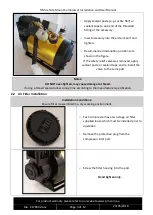
Installation Conditions:
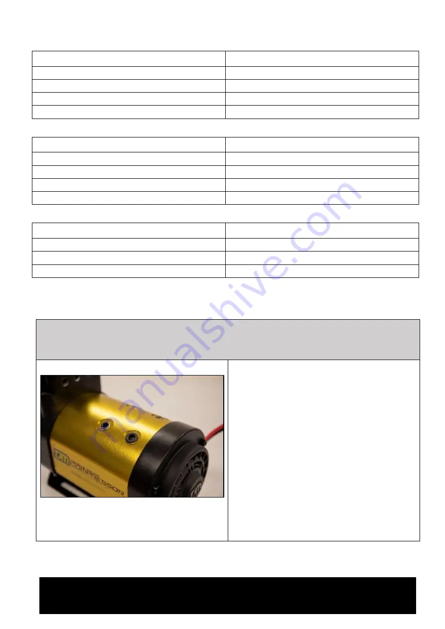
The 12 V solenoid shown is supplied with the TJM Pro Locker.
The ¼”
BSPT hose fitting shown is supplied with the TJM Airline Kit
3 x
⅛” and 1 x ¼” ports shown.
Additional ports on opposite side of air tank.
o
Determine the desired mounting
configuration for the compressor and select
the desired outlet ports for the accessories
–
there are 8 available outlet ports in total.
o
To fit the Pressure Switch and Pro-Locker
solenoids, remove one of the
⅛”
BSPT plugs in
the air tank using a 5mm hex key.
o
To fit the TJM Airline Kit, remove one of the
¼”
BSPT plugs in the air tank using a 6 mm
hex key.
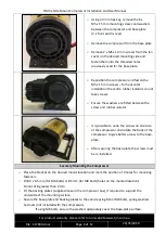
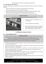
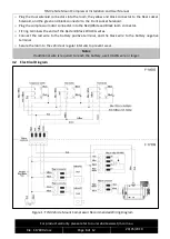
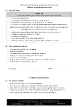
If necessary, remove the safety relief valve to
provide space for the accessory fitment.


