background image

                                                                                        8                                                  AUIA.123.00.00.00.00-05 OM 

1.4.2.4 12V DC power voltage is provided by power supply unit. 


1.4.2.5 The turnstile’s wiring diagram is shown in the Appendix C. 


1 – glass blades; 

5 –  Redibolt; 

2 – cup with drive; 


6 – 


screws М4х10; 

3 –  sheeting; 

7 – clip with plates 

4 –  control box; 


Figure 1 – Design of the rotor turnstile T3.РKC.ХC 

 
1.5 Instrumentation, tools and accessories   


Dedicated  tools  are  required  for  installation  of  the  turnstile  (multi-purpose  measurement 
instrumentation and installation tools are enough). 

1.6 Marking  


1.6.1  Marking  of  turnstiles  to  be  delivered  within  Ukraine  is  in  Ukrainian  language  and  for  export 
delivery in English.


Each turnstile is marked as follows:


name of manufacturer and trade mark; 


each turnstile is equipped with identification plate containing the following data; 


reference designation of turnstile modification; 


index of protection; 


serial number; 


value of voltage, type of current, frequency and current consumption; 


weight, kg; 


marks of conformity to     , 


date of manufacture;  


inscription «MADE IN UKRAINE». 

Marking plate is located inside the turnstile housing. 


1.6.2 Marking of transportation packing contains as follows:  
1) Information inscriptions: 


turnstile reference designation; 


dimensions of cargo package in centimeters;  

Содержание T3.PKC.XC

Страница 1: ... TiSO PRODUCTION Company SERVO OPERATED ROTOR TURNSTILE T3 РKС XC OPERATION MANUAL AUIA 123 05 OM 2013 ...

Страница 2: ...ations 16 2 2 Layout and installation 16 2 3 Preparation for use 17 2 4 Contingency actions 19 3 MAINTENANCE 19 3 1 General instructions 19 3 2 Safety measures 19 3 3 Maintenance procedure 19 4 ROUTINE MAINTENANCE 20 4 1 General instructions 20 4 2 Fault Directory 20 4 3 Post repair checkout 20 5 TRANSPORTATION AND STORAGE 20 6 UTILIZATION 20 7 MANUFACTURER S WARRANTY AND CONDITIONS OF INTERMEDIAT...

Страница 3: ...ained for operation and maintenance of the turnstile Reliability and durability of the turnstile operation is provided with observation of modes and conditions of transportation storage installation and operation So fulfillment of all requirements specified in this document is mandatory In view of regularly performed works on improvement of the product its design can be modified without degradatio...

Страница 4: ... of the turnstile it should be unpacked and its integrity should be checked In case of doubt in integrity of the turnstile it should not be used and the customer should refer to the supplier or to the manufacturer Packing accessories wooden pallet nails clips polyethylene bags cardboard etc as potential sources of hazard must be removed to unacceptable place prior to proper use of the turnstile As...

Страница 5: ...fied in the Table 2 Table 2 Operation conditions For climatic version Parameter value Ambient temperature NF4 1 С to 40 С Relative humidity 80 at 20 ºС Ambient temperature allowable pressure 84 to 106 7 kPa Transportation temperature range 40 С to 50 С Storage temperature range 5 С to 40 С Group of mechanical application L3 Altitude above sea level up to 2000 m Environment Explosion proof does not...

Страница 6: ... Design overall and installation dimensions of the turnstile are shown in Appendix A 1 3 1 2 The turnstile modifications are manufactured from the following materials polished stainless steel reference designation T3 РКC РC brushed stainless steel reference designation T3 РКC SC The turnstile s basic modification is with brushed stainless steel housing reference designation T3 РКC SC 1 3 2 Complet...

Страница 7: ... turnstile are installed in such a way that passageway between enclosures will be locked by turnstile blade 1 4 1 4 Control panel is made as small desktop device in plastic case designed for setting and indication of operating modes when the turnstile is operated manually Control panel and its connection diagram are shown in the Appendix B 1 4 2 Principle of operation 1 4 2 1 The turnstile s opera...

Страница 8: ...rking of turnstiles to be delivered within Ukraine is in Ukrainian language and for export delivery in English Each turnstile is marked as follows name of manufacturer and trade mark each turnstile is equipped with identification plate containing the following data reference designation of turnstile modification index of protection serial number value of voltage type of current frequency and curre...

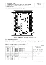
Страница 9: ...1 8 1 1 The controller is assembled on the 85х70 mm card on which electronic components and connectors for external connections are mounted 13 LED s are mounted on controller card Their purpose is as follows 8 LEDs indicate condition of inputs IN1 IN8 POWER LED indicates availability of supply voltage 5V 4 LEDs indicate condition of outputs for connection of motor 24 terminals are mounted on the c...

Страница 10: ...s coming from the controller РСВ 112 21 20 00 present position of rotor rotor rotation speed and motor current Purpose of controller s contacts is shown in the Table 6 Table 6 Connector contact No Designati on Direction Description Signal parameters and description X1 1 IN1 ENTRY Not applicable 1 logical 0 0 1 7 V 2 logical 1 3 7 5 V 3 active level of signal logical 0 4 voltage on open input 5V X1...

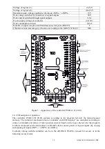
Страница 11: ...stile 1 8 2 1 Controller is assembled on card 104х68 mm and designed for installation into the turnstile housing or power supply box 19 LEDs are mounted on controller card Their purpose is as follows 5 LEDs initiate state of inputs for peripheral connections INP1 INP5 LED POWER initiates availability of power voltage 5V LED OPERATE initiates operability of microprocessor 7 LEDs initiate state of o...

Страница 12: ... the GOST 15150 69 NF4 Figure 3 Appearance of the controller РСВ 112 21 20 00 1 8 2 3 Description of operation The controller РСВ 112 21 20 00 operates according to the program fed into the microprocessor memory The turnstile s mechanism motor controller and LED displays1 are controlled according to control commands and status of rotor position sensors based on the logic entered into the program C...

Страница 13: ...wo alternatives of events are possible 1 first alternative If within active status of OPEN A В INP4 INP5 or during delay of WAITING FOR START OF ACCESS rotation of rotor is not started then controller РCВ 201 01 00 00 is reset to INITIAL STATE 2 second alternative if in the above mentioned cases rotation of rotor is started then current is delivered to motor winding via outputs MOT1 and OT2 X2 9 a...

Страница 14: ...ontroller will send the relevant command to the motor controller РCВ 201 01 00 00 to unlock rotor in both directions 2 It will switch LEDs in both directions from red to green1 3 It will initiate two delays of WAITING FOR START OF ACCESS А and В for each access separately which are counted from the moment of acquisition of commands 4 After rotor is revolved to 6º in any side the opposite direction...

Страница 15: ...ault of behaviour is detected ХТ2 8 OUT7 EXIT Not applicable ХТ3 1 OPTO1 ENTRY Used for obtaining of information about turnstile rotor position 1 logical 0 0 2 2 V 2 logical 1 3 5 V 3 active level of signal factory setting logical 0 4 voltage on open input 5V ХТ3 2 OPTO2 ENTRY ХТ3 3 OPTO3 ENTRY ХТ3 4 SGN1 ENTRY Not applicable ХТ3 5 SGN2 ENTRY ХТ3 6 SGN3 ENTRY ХТ3 7 SGN4 ENTRY ХТ3 8 INDAR EXIT Used...

Страница 16: ... BLADES OR OTHER PARTS THE PRODUCT WHICH MAY CAUSE THEIR MECHANICAL DEFORMATION OR DAMAGE 2 1 3 It is not allowed to use the turnstile at the presence of mechanical rattle in movable parts of the turnstile when metalwork of the turnstile and its components and accessories are mechanically damaged 2 1 4 List of special conditions of operation Mean time of the turnstile access in single access mode ...

Страница 17: ...es 3 check revolving of rotor rotor with blades should revolve smoothly and after revolving to 120 it should be locked When mains cable of power supply unit is connected to the network the flag rotation is locked The turnstile is set in initial state Flag with blades is locked from rotation in both directions and access between enclosures is barred by one of the blades The turnstile is set in init...

Страница 18: ...ccess in opposite direction Push the SINGLE access button to access in the selected direction A or B and the LOCK button to lock access in opposite direction Green arrow of authorized single access is lit in chosen direction and red LED display is blinking in the locked access direction Make sure that rotor can be rotated to120º in the direction of single access only once and in the direction of l...

Страница 19: ...DEVICES WHICH TERM OF CHECKING HAS ENDED 3 2 2 When instrumentations are prepared for operation it is necessary to comply with the safety requirements specified in instrumentation instruction manuals 3 3 Maintenance procedure 3 3 1 Maintenance of the turnstile includes preventive measures which are taken according to established frequency to maintain the turnstile in operational condition decreasi...

Страница 20: ...f control panel according to the Table 9 5 TRANSPORTATION AND STORAGE 5 1 It is forbidden to subject the turnstile to jerks and impacts during storage For lifting and handling of the turnstile it is necessary to use transportation trolleys In storage facility there should not be aggressive gases and vapours causing corrosion Storage ambient temperature should not be lower 5 С and higher 40 С and r...

Страница 21: ...ise specified by mutual agreement Manufacturer TiSO PRODUCTION Company 72 Yamskaya str 03680 Kiev Ukraine Tel 38 044 461 79 69 Tel Fax 38 044 586 46 47 E mail export tiso ua log1 tiso ua www tiso turnstiles com Our equipment complies with requirements of the European Standards EN ISO 12100 2010 EN 614 1 2006 A1 2009 EN 1037 1995 A1 2008 EN 60204 1 2006 EN 953 1997 A1 2009 ISO 3864 1995 EN ISO 1385...

Страница 22: ...00 00 00 05 OM Appendix А Design overall and installation dimensions of the rotor turnstile 1 central enclosure 3 servo operated turnstile 2 side enclosure 4 reader racks Figure А 1 Installation of the rotor turnstile ...

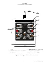
Страница 23: ...am 1 housing 5 FREE ACCESS mode control button 2 SINGLE ACCESS mode control button 3 front plate 4 LOCKING mode control button 6 PANIC mode control button 7 access direction LED display 8 controller connection terminals Figure B 1 Control panel AUIA 114 02 00 00 for turnstiles ...

Страница 24: ...24 AUIA 123 00 00 00 00 05 OM Appendix B continued Control panel and connection diagram Figure B 2 Connection diagram of the control panel AUIA 114 02 00 00 ...

Страница 25: ...25 AUIA 123 00 00 00 00 05 OM Appendix C Wiring diagram of the turnstile Figure C 1 Wiring diagram of the rotor turnstile T3 РОC XC ...

Отзывы: