5
1.2.1 Description of the PCB349 controller components
The controller
PCB349
controls operation of devices by analyzing signals from potential inputs, angular
position sensors and wire pushbutton control panel connected via interface
RS485
and sets potential outputs
depending on the Road Blocker status.
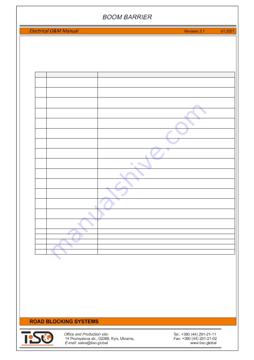
Table 1
contains description of the
PCB349
controller components
Item
Component
Purpose
1
Terminal block
X1 PS
Power Supply 230V AC
–
Terminal block for connection of controller
supply voltage
230VAC
2
Terminal block
X2 M1
Motor 1
–
Terminal block for connection of the Road Blocker1 built-in
hydraulic unit motor
3
Terminal block
X3 M2
Motor 2
–
Terminal block for connection of the Road Blocker2
built-in hydraulic unit motor
4
Fuse
F1
Fuse 1
–
Fuse
6A 250VAC
of the Road Blocker1 mini hydraulic unit
motor
5
Fuse
F2
Fuse 2
–
Fuse
6A 250VAC
of the Road Blocker2 mini hydraulic unit
motor
6
Terminal block
С1
Capacitor 1
–
Terminal block for connection of the Road Blocker1
mini hydraulic unit capacitor
С1
7
Terminal block
С2
Capacitor 2
–
Terminal block for connection of the Road Blocker2
mini hydraulic unit capacitor
С
2
8
Terminal block
X5 INP1
Inputs 1
–
Terminal block for connection of the Road Blocker 1
control inputs, sensors and additional devices
9
Terminal block
X6 OUT1
Outputs 1
–
Terminal block for connection of the Road Blocker 1
actuating devices and additional devices
10
Terminal block
X7 INP2
Inputs 2
–
Terminal block for connection of the Roa d Block er 2
control inputs, sensors and additional devices
11
Terminal block
X8 OUT2
Outputs 2
–
Terminal block for connection of the Road Blocker 2
actuating devices and additional devices
12
Terminal block
X9 RS485
Interface RS485
–
Terminal block for connection of the Road
Blocker 1 and 2 remote control panel and angular position sensors
13 Terminal block
X4 230V
TO PSU
230V to Power Supply Unit
–
Terminal block for connection of the
power supply unit voltage
230VAC
14 Terminal block
X10. 12V from PSU
12V DC from Power Supply Unit
–
Terminal block for connection of
the power supply unit voltage
12VDC
15
Switch
SW1- SW8
Switch 1-8
–
Switch of the control unit mode and configuration
parameter setting
16
Displays
LED1-LED8
Displays of mode and configuration parameters
17
Displays
LED18-LED26
Displays of the Road Blocker1 input
INP1
status
18
Displays
LED9-LED17
Displays of the Road Blocker2 input
INP2
status
19
Displays
LED33-LED38
Displays of the Road Blocker1 output
OUT1
status
20
Displays
LED27-LED32
Displays of the Road Blocker2 output
OUT2
status
Содержание Optimus RB392 Series
Страница 1: ......
Страница 25: ...25 Annex 1 Boom Barrier Connection Diagram...
Страница 26: ...26 Annex 2 Wiring Diagram of Boom Barrier with additional devices...


