28
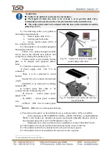
WARNING:
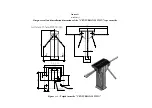
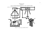
During the turnstile installation it should be taken into account that horizontally
positioned barrier rod must be at a distance not more than (50 ÷ 100) mm from
access way creator (any surface perpendicular to horizontally positioned barrier
rod: enclosure module, wall, etc.).
2.3 Preparation for use
2.3.1 Commission guidelines
Prior to the turnstile energization:
1) make sure of proper connection and good condition of all connecting cables;
2) the turnstile barrier rod turning area to be cleaned from foreign particles.
When mains cable of power supply unit is connected to network the turnstile control
mechanism are energized: barrier rods are locked from rotation in both directions barring access.
The turnstile is set in the initial state: red cross is displayed for entry and exit (« × » is lit)
.
2.3.2 Required inspections
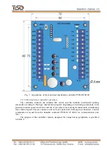
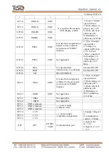
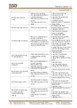
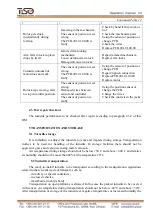
2.3.2.1 Then the turnstile is commissioned it is necessary to perform the inspections
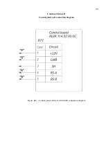
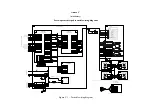
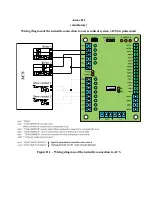
specified in Table 9. The wiring diagram according to Annex C and the control panel according
to Annex B to be used during inspection.
Table 9
Turnstile operation
mode
Operation mode setting
LED display
1
2
3
1. Turnstile is closed in both
directions (initial state)
–
Red LED is lit
2. Single access in one
direction
SINGLE button to be pushed for
access in selected direction ("A"
or "B")
Green arrow of authorized single access
is lit in selected direction and red LED
is lit in opposite direction
3. Single access in both
directions
Both SINGLE buttons to be
pushed for access in both
directions ("A" and "B")
Green arrows of authorized single
access are lit in both directions
4. Free access in one
direction
FREE button to be pushed for
access in selected direction ("A"
or "B")
Green arrow of authorized free access is
lit in selected direction and red LED is
lit in opposite direction
5. Free access in both
directions
Both FREE buttons to be pushed
for access in both directions
("A" and "B")
Green arrows of authorized free access
are lit in both directions
6. Single access in one
direction and free access in
opposite direction
SINGLE button to be pushed for
access in selected direction ("A"
or "B") and FREE button to be
pushed for access in opposite
direction
Green arrow of authorized single access
is lit in selected direction and green
arrow of authorized free access is
blinking in opposite direction
7. Single access in one
direction and locking access
in opposite direction
SINGLE button to be pushed for
access in selected direction ("A"
or "B") and LOCK button to be
pushed for blocking access in
opposite direction
Green arrow of authorized single access
is lit in selected direction and red LED
of locked access is blinking in opposite
direction

