background image

Bridge-

Box Mode d’emploi


Français 

19 / 48 


tiko Energy Solutions AG 

IM-0007-0002 Rev. 5 

Avertissements de sécurité et instructions d’utilisation


Catégories de risque 


Lisez le manuel d’utilisation avant d’installer et d’utiliser ce produit !


Installation uniquement par une personne possédant une expertise en élec-
tronique et formée à ce produit ! 


Débranchez toutes les sources d’alimentation avant d’effectuer toute mani-

pulation ! 


Utilisez toujours un équipement de protection approprié ! 


Danger ! Haute tension ! 


Ne touchez jamais les fils déconnectés ! Danger de mort ! 


Utilisez uniquement avec le courant ou la tension indiqué sur l’étiquette de 
l’appareil ! Cela pourrait endommager l’appareil et présenter un risque de dé-
charge électrique ou d’incendie !


Des vis mal serrées peuvent provoquer une résistance de contact élevée, une 

surchauffe et un risque d’incendie !


Avertissements 


Lisez les instructions d’installation avant de connecter le système à sa source d’ali-

mentation. 


Pour éviter toute surchauffe du système, ne le faites pas fonctionner dans une zone 
dépassant la température ambiante maximale autorisée de 55 °C. 


Ce produit dépend de l’installation du bâtiment pour la protection contre les courts

-

circuits (surtension). Assurez-

vous qu’un 

fusible ou un disjoncteur ne dépassant pas 

230 VCA, 10 A est utilisé sur tous les conducteurs de courant. 


Le disjoncteur doit être à l’avant, à proximité de l’appareil, facilement accessible par 
l’opérateur, et doit être marqué comme disjoncteur de déconnexion de l’appareil.


Ne travaillez pas sur le système et ne connectez pas ou ne débranchez pas les câbles 

lorsqu'il y a de l’orage.


L’appareil est destiné à être utilisé à l’intérieur uniquement.


Содержание Athos

Страница 1: ...Bridge Box Athos User s Manual CMB 01 1011 01 P1 English 2 Deutsch 10 Français 19 Italiano 28 Nederlands 37 IM 0007 0002 Rev 5 2020 05 29 tiko Energy Solutions AG ...

Страница 2: ...re haz ard Not properly tightened screws can cause a high contact resistance lead to overheating and cause a fire hazard Warnings Read the installation instructions before you connect the system to its power source To prevent the system from overheating do not operate it in an area that ex ceeds the maximum admitted ambient temperature of 55 C This product relies on the building s installation for...

Страница 3: ...gs on the enclosure are for air convection and protect the equipment from overheating Do not cover the openings Do not pour any liquid into opening This could cause fire or electrical shock Do not open the enclosure of this product and or alter this product in any way Have the equipment checked by a service professional if one of the following situations arises o The line is damaged o Liquid has e...

Страница 4: ...dge powered even in case of short circuit on the SBUS GreenPHY PLC bridge between SBUS devices and gateway M Box Status LEDs showing data link and device errors Button to hard reset the device Package Content Open the package and check that you have all the following items Instructions manual Bridge 50 cm SBUS interconnection cable or SBUS inter connector IMAGE 2 Clip A and Covers B and C IMAGE 3 ...

Страница 5: ... of the installation Chain as many devices to the right side of the Bridge as required for the installation An SBUS is connected in one of the 2 ways Using the SBUS interconnector Plug the SBUS connector in one of the devices and slide the Bridge along the DIN rail to wards it IMAGE 6 Use the Clip A to prevent the SBUS from being disconnected IMAGE 7 Using the SBUS cable Connect the Bridge to the ...

Страница 6: ...ers a firmware up grade of the device Any further operation of the Bridge is subject to the control of the full system and oper ated by the Data Center through the Gateway M Box No user interaction is required LED Explanation The Bridge features two LEDs a red LED at the top and a green LED at the bottom In normal operation Color Status Notes Top LED Steady Green PLC connection ac tive incoming tr...

Страница 7: ...eep in mind that other devices of the tiko installation need the Bridge to run Step 3 Put the cover panel back Ensure that no electrical contact can be touched Step 4 Power on the system Step 5 If the device remains property of tiko Energy Solutions AG or its authorized reseller it must be returned Otherwise the ultimate disposal of a device shall be handled according to national laws and regulati...

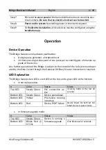
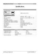
Страница 8: ...Overvoltage Category OVC II Voltage of breaker before the Bridge max 230 V Current of breaker before the Bridge max 10 A Connectivity PLC HomePlug GreenPHY User Interface 1 push button 2 bi color LEDs Dimensions 94 x 66 x 38 mm Weight 120 g Hardware Revision 1 0 1 Operating Conditions Storage Conditions Temperature min 10 C 20 C Temperature max 55 C 70 C Relative Humidity 10 85 no condensation 5 9...

Страница 9: ...ion tiko Energy Solutions AG Pflanzschulstrasse 7 CH 8004 Zürich info tiko energy The product CMB 01 1011 01 P1 in the form as delivered conforms to the provisions of the following European directives 2011 65 EU on hazardous substances 2014 35 EU on low voltage devices 2014 30 EU on electromagnetic compatibility 2014 53 EU on radio equipment A copy of the declaration of conformity can be requested...

Страница 10: ...r zu Überhitzung und Brandgefahr führen kann Warnungen Lesen Sie die Installationsanweisungen bevor Sie dieses Gerät an eine Stromquelle anschliessen Um das System vor Überhitzung zu schützen betreiben Sie es nicht in einer Umge bung welche die Temperatur von 55 C übersteigt Dieses Produkt ist auf das Vorhandensein eines Kurzschlussschutzes im Gebäude angewiesen Stellen Sie sicher dass alle stromf...

Страница 11: ... Brand oder Elektroschock führen Öffnen Sie weder das Gehäuse dieses Gerätes noch modifizieren Sie es auf irgend eine Weise Lassen Sie das Gerät bei einem professionellen Service Techniker überprüfen sollte eine der folgenden Bedingungen auftreten o Die Leitung ist beschädigt o Flüssigkeit ist ins Gerät eingedrungen o Das Gerät wurde Feuchtigkeit ausgesetzt o Das Gerät funktioniert nicht einwandfr...

Страница 12: ...er supply unit PSU für SBUS Geräte mit ca 10 W 5 VDC mit Kurzschluss und Überlastschutz Unabhängiger Kurzschluss Überlastschutz um die Bridge auch im Falle eines Kurzschlusses auf dem SBUS weiter zu betreiben GreenPHY PLC powerline communication Kommunikationsschnittstelle für andere SBUS Geräte über Stromkabel zum Gateway M Box Status LED zur Anzeige der Verbindung und von Gerätefehlern Taster um...

Страница 13: ...indeutige Seriennummer MAC Adresse als Text und Aztec Code SN MAC Installation Installation ausschliesslich durch Person mit Sachkenntnis in Elektronik und auf diesem Produkt geschult Gerät nicht installieren solange nicht die Hauptstromversorgung ab ge schaltet ist Hauptschalter oder Sicherung Installation der Bridge Schritt 1 Schalten Sie im Verteilkasten den Strom ab Schritt 2 Entfernen Sie die...

Страница 14: ...n Sie die Bridge durch das SBUS Kabel mit dem anderen Gerät Warnung SBUS Kabel dürfen nicht nahe stromführenden Kabeln durchführen Minima ler Abstand beträgt 10 mm Benützen Sie Abdeckung B und Abdeckung C BILD 3 um die linken Öffnungen der Bridge zu verschliessen BILD 8 Schritt 5 Verkabeln Sie nun die Bridge BILD 9 Klemmen Sie die Phase in die linke Klemme Klemmen Sie den Neutralleiter in die rech...

Страница 15: ...griff des Benutzers nötig LED Legende Die Bridge verfügt über zwei LEDs ein rotes LED oben und ein grünes LED unten Im Normalbetrieb Farbe Status Bemerkungen Oberes LED Grün PLC Verbindung zur M Box aktiv Datenübertragung innerhalb der letzten 60 Sekunden Unteres LED Grün Gerät in Betrieb Unteres LED Gelb Primäre Stromver sorgung defekt Läuft auf der redun danten Stromver sorgung Unteres LED Rot G...

Страница 16: ...f die Bridge angewiesen sind Schritt 3 Bringen Sie die Abdeckungen im Verteilkasten wieder an um die Kon takte zu bedecken Stellen Sie sicher dass kein elektrischer Kontakt be rührt werden kann Schritt 4 Schalten Sie das System ein indem Sie im Verteilkasten den Strom wie der einschalten Schritt 5 Bleibt das Gerät Eigentum der tiko Energy Solutions AG oder des autorisierten Händlers muss es zurück...

Страница 17: ...Überspannungsschutz Klasse II Spannung Schutzschalter vor der Bridge max 230 V Strom Schutzschalter vor der Bridge max 10 A Konnektivität PLC HomePlug GreenPHY Bedienoberfläche 1 Taster 2 zweifarbige LEDs Abmessungen 94 x 66 x 38 mm Gewicht 120 g Hardware Revision 1 0 1 Betriebsbedingungen Lagerbedingungen Temperatur min 10 C 20 C Temperatur max 55 C 70 C Relative Luftfeuchtigkeit 10 85 kein Konde...

Страница 18: ...s AG genehmigten Installationen Sicherheitshinweise tiko Energy Solutions AG Pflanzschulstrasse 7 CH 8004 Zürich info tiko energy Das Produkt CMB 01 1011 01 P1 entspricht im Lieferzustand den Vorschriften der fol genden europäischen Richtlinien 2011 65 EU zu gefährlichen Substanzen 2014 35 EU zu Niederspannungsgeräten 2014 30 EU zu elektromagnetischer Verträglichkeit 2014 53 EU zu Radiogeräten Ein...

Страница 19: ...ndie Des vis mal serrées peuvent provoquer une résistance de contact élevée une surchauffe et un risque d incendie Avertissements Lisez les instructions d installation avant de connecter le système à sa source d ali mentation Pour éviter toute surchauffe du système ne le faites pas fonctionner dans une zone dépassant la température ambiante maximale autorisée de 55 C Ce produit dépend de l install...

Страница 20: ...convection de l air et protègent l équi pement contre la surchauffe Ne couvrez pas les ouvertures Ne versez pas de liquide dans l ouverture Cela pourrait provoquer un incendie ou une décharge électrique N ouvrez pas le boîtier de ce produit et ou n apportez aucune modification à ce produit Faites vérifier l équipement par un professionnel si l une des situations suivantes se présente o La ligne es...

Страница 21: ... pour les appareils SBUS à la source env 10 W 5 VCC avec protection contre les courts circuits et les surcharges Protection indépendante contre les courts circuits et les surcharges sur le SBUS pour maintenir le Bridge sous tension même en cas de court circuit sur le SBUS Pont GreenPHY API entre les appareils SBUS et la passerelle M Box Voyants d état indiquant les erreurs de liaison de données et...

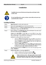
Страница 22: ... firmware FW L adresse série MAC unique sous forme de texte et de code 2D Aztec SN MAC Installation Installation uniquement par une personne possédant une expertise en électronique et formée à ce produit N installez pas l appareil avant d avoir débranché l alimentation princi pale disjoncteur principal ou fusibles Installer le Bridge Étape 1 Coupez l alimentation du panneau électrique Étape 2 Reti...

Страница 23: ...ourni Attention les câbles SBUS ne doivent pas se trouver à proximité des câbles d alimentation Le dégagement minimum est de 10 mm Utilisez les caches B et C IMAGE 3 pour fermer les ouvertures gauches du Bridge IMAGE 8 Étape 6 Connectez les fils au Bridge IMAGE 9 Connectez une phase à la borne gauche Connectez un neutre à la borne de droite Serrez toutes les vis de serrage au couple approprié Une ...

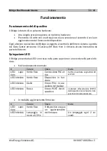
Страница 24: ...ntion de l utilisateur n est nécessaire Explication des voyants Le Bridge dispose de deux voyants un voyant rouge en haut et un voyant vert en bas En fonctionnement normal Couleur État Notes Voyant du haut Vert fixe Connexion API ac tive Trafic entrant dans les 60 der nières secondes Voyant du bas Vert fixe Appareil opération nel Voyant du bas Jaune Échec du PSU exé cution en sauve garde Voyant du...

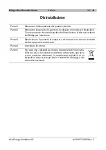
Страница 25: ...d autres appareils de l installation tiko ont besoin du Bridge pour fonctionner Étape 3 Replacez le cache de protection Assurez vous qu aucun contact élec trique ne peut être touché Étape 4 Mettez le système sous tension Étape 5 Si l appareil reste la propriété de tiko Energy Solutions AG ou de son revendeur agréé il doit être rendu Sinon l élimination finale d un appareil doit être effectuée conf...

Страница 26: ...égorie de surtension OVC II Tension du disjoncteur avant le Bridge max 230 V Courant du disjoncteur avant le Bridge max 10 A Connexité PLC HomePlug GreenPHY Interface Utilisateur 1 bouton 2 bi couleur voyants Dimensions 94 x 66 x 38 mm Poids 120 g Révision du matériel 1 0 1 Conditions d exploitation Conditions de rangement Température min 10 C 20 C Température max 55 C 70 C Humidité relative 10 85...

Страница 27: ...s de sécurité tiko Energy Solutions AG Pflanzschulstrasse 7 CH 8004 Zürich info tiko energy Les produits CMB 01 1011 01 P1 sous leur forme livrée sont conformes aux dispositions des directives européennes suivantes 2011 65 EU sur les substances dangereuses 2014 35 EU sur les appareils à basse tension 2014 30 EU sur la compatibilité électro magnétique 2014 53 EU sur les équipements radio Une copie ...

Страница 28: ...ti non serrate correttamente possono causare un elevata resistenza di contatto provocare il surriscaldamento e causare incendi Avvertenze Leggere le istruzioni di installazione prima di collegare il sistema all alimentazione Per evitare il surriscaldamento del sistema non utilizzarlo in un area con temperatura eccedente quella ambiente massima consentita di 55 C La protezione contro i cortocircuit...

Страница 29: ...ervono per la convezione dell aria e proteggono l appa recchiatura dal surriscaldamento Non coprire le aperture Non versare alcun liquido nelle aperture Ciò potrebbe causare incendi o scosse elet triche Non aprire l involucro di questo prodotto e o alterare questo prodotto in alcun modo Far controllare l apparecchiatura da un tecnico dell assistenza se si verifica una delle seguenti situazioni o L...

Страница 30: ... SBUS per erogare ca 10 W a 5 VCC con protezione da cortocircuito e sovraccarico protezione indipendente da cortocircuito sovraccarico su SBUS per mantenere il Bridge alimentato anche in caso di cortocircuito su SBUS Bridge PLC GreenPHY tra dispositivi SBUS e gateway M Box LED di stato che indicano errori di connessione dati ed errori del dispositivo Pulsante per ripristinare il dispositivo Conten...

Страница 31: ...voco in formato testuale e come codice 2D Aztec SN MAC Installazione L installazione deve essere effettuata esclusivamente da personale con esperienza elettronica e istruita su questo prodotto Non installare il dispositivo a meno che non sia stata rimossa l alimenta zione principale interruttore principale o fusibili Installazione del Bridge Punto 1 Rimuovere l alimentazione dal quadro elettrico P...

Страница 32: ... SBUS in dotazione Avvertenza i cavi SBUS non devono essere vicini ai cavi di alimentazione La distanza mi nima è di 10 mm Utilizzare il coperchio B e il coperchio C IMMAGINE 3 per chiudere le aperture a sinistra del Bridge IMMAGINE 8 Punto 6 Collegare i conduttori al Bridge IMMAGINE 9 Collegare una fase al morsetto terminale sinistro Collegare un neutro al morsetto terminale destro Stringere tutt...

Страница 33: ...e dell utente Spiegazione LED Il Bridge presenta due LED uno rosso nella parte superiore e uno verde nella parte infe riore Nel funzionamento normale Colore Stato Note LED supe riore Verde fisso Connessione PLC at tiva traffico in entrata negli ultimi 60 secondi LED inferiore Verde fisso Dispositivo in fun zione LED inferiore Giallo Errore PSU in ese cuzione nel backup LED inferiore Rosso Errore P...

Страница 34: ...ll installazione di tiko necessitano del Bridge per funzionare Punto 3 Riposizionare il pannello di copertura Assicurarsi che nessun contatto elettrico possa essere toccato Punto 4 Accendere il sistema Punto 5 Nel caso che il dispositivo rimane di proprietà di tiko Energy Solutions AG o del relativo rivenditore autorizzato egli deve essere restituito Altrimenti lo smaltimento definitivo di un disp...

Страница 35: ...atensione OVC II Tensione dell interruttore automatico a monte del Bridge max 230 V Corrente dell interruttore automatico a monte del Bridge max 10 A Connettività PLC HomePlug GreenPHY Interfaccia Utente 1 pulsante 2 bi color LED Dimensioni 94 x 66 x 38 mm Peso 120 g Revisione hardware 1 0 1 Condizioni operative Condizioni di stoccaggio Temperatura min 10 C 20 C Temperatura max 55 C 70 C Umidità r...

Страница 36: ...rezza tiko Energy Solutions AG Pflanzschulstrasse 7 CH 8004 Zürich info tiko energy Il prodotto CMB 01 1011 01 P1 nella forma consegnata è conforme alle disposizioni delle seguenti direttive europee 2011 65 UE sulle sostanze pericolose 2014 35 UE sui dispositivi a bassa tensione 2014 30 UE sulla compatibilità elettromagnetica 2014 53 EU sui dispositivi di apparecchiature radio Una copia della dich...

Страница 37: ...de schroeven kunnen een hoge contactweerstand oververhitting en brand veroorzaken Waarschuwingen Lees de installatie instructies voordat u het systeem op de stroombron aansluit Om te voorkomen dat het systeem oververhit raakt mag u het niet gebruiken in een ruimte die de maximaal toegelaten omgevingstemperatuur van 55 C overschrijdt Dit product is afhankelijk van de installatie van het gebouw voor...

Страница 38: ...uizing zijn voor luchtconvectie en beschermen de apparatuur tegen oververhitting Dek de openingen niet af Giet geen vloeistof in de opening Dit kan brand of een elektrische schok veroorza ken Open de behuizing van dit product niet en of wijzig dit product op geen enkele ma nier Laat de apparatuur controleren door een servicemedewerker als zich een van de vol gende situaties voordoet o Het snoer is...

Страница 39: ... voor SBUS apparaten om ca 10 W 5 VDC met be scherming tegen kortsluiting en overbelasting onafhankelijke kortsluit overbelastingsbeveiliging op de SBUS te voeden om de Bridge gevoed te houden zelfs in geval van kortsluiting op de SBUS GreenPHY PLC brug tussen SBUS apparaten en gateway M Box status LED s met gegevensverbinding en apparaatfouten Drukknop om het apparaat hard te resetten Inhoud van ...

Страница 40: ...tbare belasting De hardware HW en firmware FW versie Het unieke seriële MAC adres als tekst en als Aztec 2D code SN MAC Installatie Installatie door persoon met elektronische expertise en alleen getraind op dit product Installeer het apparaat niet tenzij u de hoofdvoeding hebt verwijderd hoofdschakelaar of zekeringen De Bridge installeren Step 1 Verwijder de stroom van het elektrische paneel Step ...

Страница 41: ... met behulp van de meegeleverde SBUS ka bel Waarschuwing SBUS kabels mogen niet in de buurt van stroomkabels liggen Minimale vrije ruimte is 10 mm Gebruik Afdekking B en Afdekking C AFBEELDING 3 om de lin keropeningen van de Bridge te sluiten AFBEELDING 8 Stap 6 Verbind de draden met de Bridge AFBEELDING 9 Sluit een fase aan op de linker aansluitklem Sluit een nulleider aan op de juiste aansluitkl...

Страница 42: ...de gateway M Box Geen gebrui kersinteractie vereist LED toelichting De Bridge heeft twee LED s een rode LED bovenaan en een groene LED onderaan Tijdens normaal bedrijf Kleur Status Notities Bovenste LED Constant groen PLC verbinding ac tief inkomend verkeer in de laatste 60 seconden Onderste LED Constant groen Apparaat operatio neel Onderste LED Geel PSU fout actief in back up Onderste LED Rood Ap...

Страница 43: ...ng mee dat andere apparaten van de tiko installatie de Bridge nodig hebben Stap 3 Plaats het afdekpaneel terug Zorg dat er geen elektrisch contact kan worden aangeraakt Stap 4 Het systeem inschakelen Stap 5 Als het apparaat blijft eigendom van tiko Energy Solutions AG of zijn geautoriseerde wederverkoper moet het worden ge retourneerd Anders moet de uiteindelijke afvoer van een ap paraat volgens d...

Страница 44: ...e 50 Hz Overspanningscategorie OVC II Voltage van onderbreker vóór de Bridge max 230 V Stroom van onderbreker vóór de Bridge max 10 A Verbinding PLC HomePlug GreenPHY Gebruikersinterface 1 drukknop 2 tweekleurige LED s Afmetingen 94 x 66 x 38 mm Gewicht 120 g Hardwarerevisie 1 0 1 Bedrijfsvoorwaarden Opslagcondities Temperatuur min 10 C 20 C Temperatuur max 55 C 70 C Relatieve vochtigheid 10 85 ge...

Страница 45: ...ergy Solutions AG Pflanzschulstrasse 7 CH 8004 Zürich info tiko energy Het product CMB 01 1011 01 P1 in de vorm zoals geleverd voldoet aan de bepalingen van de volgende Europese richtlijnen 2011 65 EU betreffende gevaarlijke stoffen 2014 35 EU betreffende laagspanningsapparatuur 2014 30 EU betreffende elektro magnetische compatibiliteit 2014 53 EU betreffende apparaten met radioapparatuur Een kopi...

Страница 46: ...Notes Notizen Notes Note Opmerkingen 46 48 tiko Energy Solutions AG IM 0007 0002 Rev 5 ...

Страница 47: ...Notes Notizen Notes Note Opmerkingen 47 48 tiko Energy Solutions AG IM 0007 0002 Rev 5 ...

Страница 48: ...Bridge Box User s Manual 48 48 tiko Energy Solutions AG IM 0007 0002 Rev 5 Line in Neutral in ...

Отзывы: