Synergy Controller Technical Manual, Revision H
Page 130
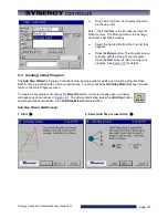
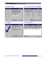
After pressing the
Finish
button, the program screen displays your new step. Verify your entry and continue
adding, inserting, or copying steps as necessary to complete your program.
Press the
Save File
button when you are through creating your program.
Notes
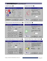
Step 3 Note: You may want a Stop step at the end of your program. If you do not include a stop step at the
end of a program the controller will shut down the chamber when the program completes.
Step 9 Note: During humidity control, turn on OT11 TPM to change Output 11 (Ambient Coil) from On/Off
control to Time Proportioned control.
9.3 Step Type Descriptions
The Synergy Controller can be used to create complex temperature and humidity profiles. It supports five
different step types; each step type has a specific function. These five steps are: Setpoint, Jump Loop,
Waitfor, Auto Start and Stop. The step type is selected in the Select Step Type screen of the
Add Step
Wizard
, as seen in step #3 above. Each step is described in detail below.
♦
Setpoint:
The Setpoint step is used to ramp the chamber from one setpoint to another or to soak at a
setpoint for a specific time period. Setpoints can be used to change events or logical values.
Some fields are required in a setpoint step and some are not. Temperature setpoint is always
required, even if it is the same as the previous step. Channel 2, 3 or 4, if present, can be set, or turned
off and not controlled.
If a ramp time is desired it can be entered. If no time is entered, the setpoint will immediately go to the
desired setting and the profile will continue. If a ramp time is set, the setpoint will ramp linearly from
the starting point to the desired setpoint throughout the step. For example, if the user wants to ramp
the temperature ten degrees in ten minutes, the chamber will drive the temperature one degree higher
every minute.
Output Events are programmable for each step. These events can be enabled or disabled with every
setpoint step if some user function or hardware is connected to one or more event outputs. Events are
evaluated at the beginning of every step. If an event is set on for a step, it is enabled at the beginning
of the step and maintained for the duration of the step.
The last set of options in a Setpoint step is located on the events screen. They are Use Drier, LEV2,
and OT11. Use Drier enables the drier device (if available) on temperature/humidity chambers instead
of the default dehumidify coil. When equipped with a drier device the chamber will typically be capable
of achieving a lower humidity. OT11 changes the output logic for the ambient coil between On/Off
logic and Time Proportioning logic. LEV2 controls the Purge device (if available and enabled through
OT17). Enabling it will enable the purge device, disabling it will disable the purge device.
of the manual for more information regarding these control features.
♦
Jump Loop:
The Jump-loop step is used to repeat parts of a profile. A Jump-loop step requires two
parameters; the target step for the loop, and the number of times to jump. The target step must always
be before the jump step because the controller cannot jump forward; it will only jump back in the
profile. The jump count specifies how many times to loop back over the steps. The count can be
anywhere from one to two hundred fifty five, or negative one. Negative one specifies an infinite loop; it
will continue jumping back to the specified step until the profile is stopped manually. Specify the
required number of cycles less one when specifying the jump loop count since the steps will always be
executed once before the first jump.
Содержание Synergy Compact
Страница 14: ...Synergy Controller Technical Manual Revision H Page 14 2 0 SPECIFICATIONS 2 1 Data Sheet...
Страница 71: ...Synergy Controller Technical Manual Revision H Page 71...
Страница 106: ...Synergy Controller Technical Manual Revision H Page 106...
Страница 123: ...Synergy Controller Technical Manual Revision H Page 123...
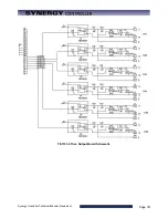
Страница 141: ...Synergy Controller Technical Manual Revision H Page 141 TE1151 6 Triac Output Board Schematic...
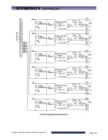
Страница 142: ...Synergy Controller Technical Manual Revision H Page 142 TE1708 6 Relay Board Schematic...
Страница 188: ...Synergy Controller Technical Manual Revision H Page 188...
Страница 274: ...Synergy Controller Technical Manual Revision H Page 274 Synergy Controller Step Syntax...
Страница 294: ...Synergy Controller Technical Manual Revision H Page 294...
Страница 312: ...Synergy Controller Technical Manual Revision H Page 312...
Страница 345: ...Synergy Controller Technical Manual Revision H Page 345...
Страница 346: ...Synergy Controller Technical Manual Revision H Page 346...


