Synergy Controller Technical Manual, Revision H
Page 101
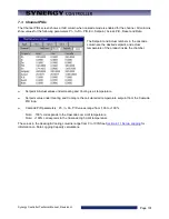
7.3 Channel PIDs
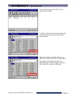
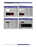
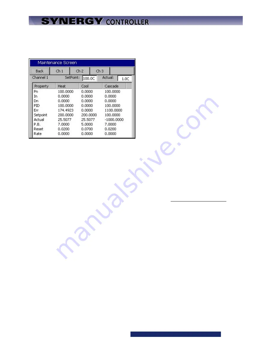
The Channel PIDs screen shows a third column when cascade mode is enabled for the channel. All columns
show values for the following parameters: Pn, In, Dn, PID, Err, Setpoint, Actual, P.B., Reset and Rate.
The Setpoint and Actual numbers in the cascade
column are the desired setpoint, and actual
temperature of the product inside the chamber.
♦
Setpoint & Actual values under Heating and Cooling is air temperature.
♦
Setpoint value under Heating and Cooling is the calculated air temperature setpoint from the Cascade
PID loop.
♦
Cascade PID parameters: Pn, In, Dn, PID values range from -100 to +100%.
Note: -100% corresponds to the Cascade Low Limit temperature
Note: +100% corresponds to the Cascade High Limit temperature
The values in the Heating & Cooling columns range from 0 to 100%See
information on Data Logging Capacity calculations.
Содержание Synergy Compact
Страница 14: ...Synergy Controller Technical Manual Revision H Page 14 2 0 SPECIFICATIONS 2 1 Data Sheet...
Страница 71: ...Synergy Controller Technical Manual Revision H Page 71...
Страница 106: ...Synergy Controller Technical Manual Revision H Page 106...
Страница 123: ...Synergy Controller Technical Manual Revision H Page 123...
Страница 141: ...Synergy Controller Technical Manual Revision H Page 141 TE1151 6 Triac Output Board Schematic...
Страница 142: ...Synergy Controller Technical Manual Revision H Page 142 TE1708 6 Relay Board Schematic...
Страница 188: ...Synergy Controller Technical Manual Revision H Page 188...
Страница 274: ...Synergy Controller Technical Manual Revision H Page 274 Synergy Controller Step Syntax...
Страница 294: ...Synergy Controller Technical Manual Revision H Page 294...
Страница 312: ...Synergy Controller Technical Manual Revision H Page 312...
Страница 345: ...Synergy Controller Technical Manual Revision H Page 345...
Страница 346: ...Synergy Controller Technical Manual Revision H Page 346...

