


INTRODUCTION
9
—
Product identification
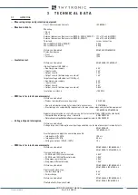
Each device is equipped with:
• Identification label installed on the front side with following informations: code number, phase and
residual nominal currents, auxiliary voltage range and CE mark
[1]
:
• Test label with following informations: data, serial number and test operator signature
[2]
.
—
Environment
The XMR device must be employed according to the environment conditions shown (see technical
data).
In case of different environment conditions, appropriate provisions must be provided (conditioning
system, humidity control, etc...).
If contaminants are present (dust, corrosive substances, etc...), filters must be provided.
—
Graphical conventions
The CEI/IEC and ANSI symbols is employed where possible:
e.g.: 51 = ANSI code concerning the overcurrent element.
Following text formats are used:
The Thyvisor menu:
Phase overcurrent -50/51
The parameter description (measures, thresholds, operate time,...) and related value:
I> element
Definite time
I>def
The display messages (MMI) are shown as:
XMR-x
Notes are highlighted with cursive letters inside colored bar
—
Glossary/definitions
f
n
Rated frequency
I
nH
Relay phase rated current side H
I
npH
Phase CT primary rated current side H
I
nL
Relay phase rated current side L
I
npL
Phase CT primary rated current side L
I
ng
Protected device rated current
I
En1
Relay residual rated current (input 1)
I
Enp1
Residual CT primary rated current (input 1)
I
En2
Relay residual nominal current (input 2)
I
Enp2
Residual CT primary nominal current (input 2)
ANSI codes:
21
Underimpedance
24
Over Flux(V/Hz)
25 SynchroCheck
26
Thermal with Pt100 probes
27 Undervoltage
27V1
Positive sequence undervoltage
32P
Directional active overpower
32Q
Directional reactive overpower
37 Undercurrent
37P
Directional active underpower
37Q
Directional reactive underpower
40
Loss of field
46LT
Negative sequence overcurrent transformer
46M-46G
Negative sequence overcurrent
I2/I1
Negative /positive sequence current ratio
47
Phase reversal
49LT
Thermal Image Transformer
49MG
Thermal image
50/27
Unintentional energisation at standstill protection
50/51
Phase overcurrent side H and side L
50N/51N
Maximum Residual Overcurrent
50N(Comp)/51N(Comp)
Calculated residual overcurrent
Note 1 The rating data can be found on labels on the back and on the front (accessible after removing the left frame)
Note 2 The rating data can be found on labels on the front plate (accessible after removing the right frame)
XMR0#000000000
I
n
5A
U
AUX
110-230 Vac/dc
100V
100V
I
En
U
En
U
n
1A
1A
5A
1A
5A
XMR-D EQUIPMENT MANUAL
Ed. 2.9 - 02/2021


