


MEASURES, LOGIC STATES AND COUNTERS
357
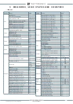
5 M E A S U R E S , L O G I C S T A T E S A N D C O U N T E R S
—
Measures
Typology
Measure
Symbol
Direct
Locked frequency
f
l
Phase to Phase voltage frequency
f
U12
, f
U23
, f
U31
Phase currents (Side L - SideH)
I
L1L
, I
L2L
, I
L3L
I
L1H
, I
L2H
, I
L3H
RMS value of fundamental comp. for phase currents (Side L)
I
L1Lrms
, I
L2Lrms
, I
L3Lrms
RMS value of fundamental comp. for phase voltages
U
L1
, U
L2
, U
L3
V
2
voltage
V
2
RMS value of fundamental com. for residual current 1
I
E1
RMS value of fundamental com. for residual current 2
I
E2
RMS value of fundamental com. for residual voltage
U
E
L1 phase
Compensated phase current (Side L - Side H)
I
L2cL
I
L2cH
Stabilization phase current
I
SL2
Differential phase current
I
DL2
2
nd
harmonic of differential phase current
I
DL2-2nd
5
th
harmonic of differential phase current
I
DL2-2th
L2 phase
Compensated phase current (Side L - Side H)
I
L3cL
I
L3cH
Stabilization phase current
I
SL3
Differential phase current
I
DL3
2
nd
harmonic of differential phase current
I
DL3-2nd
5
th
harmonic of differential phase current
I
DL3-2th
L3 phase
Compensated phase current (Side L - Side H)
I
L1cL
I
L1cH
Stabilization phase current
I
SL1
Differential phase current
I
DL1
2
nd
harmonic of differential phase current
I
DL1-2nd
5
th
harmonic of differential phase current
I
DL1-2th
Calculated
Phase-to-phase voltages
U
12
, U
23
, U
31
Calculated residual voltage
U
EC
Calculated residual current (Side L - Side H)
I
ECL
I
ECH
Stabilization current (Side H)
I
ESH
Thermal image
DThetaL
DThetaH
DThetaMG
Flux U
max/f
U/f
Frequency rate of change
df/dt
Field to ground resistence
RF
Maximum current between I
L1L
-I
L2L
-I
L3L
I
LmaxL
Minimum current between I
L1L
-I
L2L
-I
L3
I
LminL
Average current between I
L1L
-I
L2L
-I
L3
I
LL
Maximum current between I
L1H
-I
L2H
-I
L3H
I
LmaxH
Minimum current between I
L1H
-I
L2H
-I
L3H
I
LminH
Average current between I
L1H
-I
L2H
-I
L3H
I
LH
Maximun RMS current between I
L1Lrms
-I
L2Lrms
-I
L3Lrms
I
LmaxL-rms
Minimum RMS current between I
L1Lrms
-I
L2Lrms
-I
L3Lrms
I
LminL-rms
Average current between I
L1Lrms
-I
L2Lrms
-I
L3Lrm
I
L
Maximum voltage between U
L1
-U
L2
-U
L3
U
Lmax
Minimum voltage between U
L1
-U
L2
-U
L3
U
Lmin
Average voltage between U
L1
-U
L2
-U
L3
U
L
Maximum voltage between U
12
-U
23
-U
31
U
max
Minimum voltage between U
12
-U
23
-U
31
U
min
Average voltage between U
12
-U
23
-U
31
U
Typology
Measure
Symbol
Displacement
Displacement angle of I
L1L
respect to U
L1
PhiL1
Displacement angle of I
L2L
respect to U
L2
PhiL2
Displacement angle of I
L3L
respect to U
L3
PhiL3
Displacement angle of I
L1L
respect to U
23
Alpha1
Displacement angle of I
L2L
respect to U
31
Alpha2
Displacement angle of I
L3L
respect to U
12
Alpha3
Displacement angle of U
E
respect to I
E2
PhiE
Displacement angle of U
EC
respect to I
E2
PhiEC
Displacement angle of U
E
respect to I
ECL
/I
ECH
PhiE-I
EC(L /H)
Displacement angle of U
EC
respect to I
ECL
/I
ECH
PhiEC-I
EC(L /H)
Sequence
Positive sequence current (Side L)
I
1L
Negative sequence current (Side L)
I
2L
Negative sequence/positive sequence current ratio (Side L)
I
2L
/I
1L
Positive sequence current (Side H)
I
1H
Negative sequence current (Side H)
I
2H
Negative sequence/positive sequence current ratio (Side H)
I
2H
/I
1H
Positive sequence voltage
U
1
Negative sequence voltage
U
2
Power
Total active power
P
Total reactive power
Q
Total apparent power
S
Power factor
cosPhi
L
1
, L
2
, L
3
Phase active powers
P
L1
, P
L2
, P
L3
L
1
, L
2
, L
3
Phase reactive powers
Q
L1
, Q
L2
, Q
L3
L
1
, L
2
, L
3
Phase power factor
CosPhiL
1...3
Impedance
Resistive component of L
1
phase impedance
R
L1
Reactive component of L
1
phase impedance
X
L1
L
1
phase impedance
Z
L1
Phase to Phase impedance
Z
12
, Z
23
, Z
31
2
nd
Harmonic
2
nd
harmonic of phase currents (Side L - Side H)
I
L1L...3-2nd
I
L1H...3-2nd
Max of the 2
nd
harmonic phase currents/Fundamental
component percentage ratio I
-2nd
/I
L
(Side L - Side H)
I
-2ndL
/I
LL
I
-2ndH
/ I
LH
3
rd
Harmonic
3
rd
harmonic of phase currents (Side L - Side H)
I
L1L...3-3rd
I
L1H...3-3rd
3
rd
harmonic of residual currents (I
E1
- I
E2
)
I
E1-3rd
I
E2-3rd
3
rd
harmonic of residual voltage
U
E-3rd
4
th
Harmonic
4
th
harmonic of phase currents (Side L - Side H)
I
L1L...3-4th
I
L1H...3-4th
5
th
Harmonic
5
th
harmonic of phase currents (Side L - Side H)
I
L1L...3-5th
I
L1H...3-5th
Synchro check
V
1
voltage
V
1
V
2
voltage
V
2
V
1
frequency
fV
1
V
2
frequency
fV
2
V
1
V
2
voltage difference
DV
V
1
V
2
frequency difference
Df
Displacement angle of V
2
respect to V
1
Phi V
1
V
2
Demand
phase
(Side L - Side
H)
Phase fixed currents demand
I
L1...3FIXL
I
L1...3FIXH
Phase rolling currents demand
I
L1...3ROLL
I
L1...3ROLH
Phase peak currents demand
I
L1...3MAXL
I
L1...3MAXH
Phase minimum currents demand
I
L1...3MINL
I
L1...3MINH
Demand
power
Fixed active power demand
P
FIX
Fixed reactive power demand
Q
FIX
Rolling active power demand
P
ROL
Rolling reactive power demand
Q
ROL
Maximum active power demand
P
MAX
Maximum reactive power demand
Q
MAX
Minimum active power demand
P
MIN
Minimum reactive power demand
Q
MIN
XMR-D EQUIPMENT MANUAL
Ed. 2.9 - 02/2021


