


294
FUNCTION CHARACTERISTICS
—
Out of Step - 78
Preface
The out of step (OOS) of a synchronous generator related to electrical system can occur as a result
of generator excitation malfunction or due to electrical system instability in case of network faults
delayed extinction, line energization transients or loads disconnection/insertion.
Out of step events caused by excitation system malfunctions present electromechanical oscillation
phenomena relatively contained and bearable by generating sets. In any case, loss of excitation pro-
tection (40) is able to effectively detect malfunctions of this type and to operate the delayed discon-
nection of the generator from network.
On the contrary, when exciter generator is operating correctly, OOS events related to disturbances in
electrical system can produce significant fluctuations of main voltage and critical electromechanical
oscillations due to the exchanges of active and reactive power among groups. In order to ward off
these phenomena, in case of relevant electrical system generators, it’s necessary to provide a dedi-
cated protection against out of step.
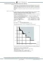
Furthermore, this protection must be able to recognize OOS events (non-recoverable system pertur-
bation, so unstable system) from system power swing phenomena (damped system perturbations with
subsequent stable mode network operation restoration).
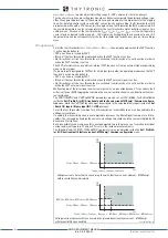
Protection 78 is designed for synchronous generators out of step and it cannot be used as protection
of synchronous machines used as motors.
Reference model
Out of step is a complex phenomenon whose study requires the use of complex network models and
numerical simulations. The phenomenon is described using the simplified two-machine network mo-
del in order to present the 78 available parameters settings.
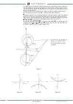
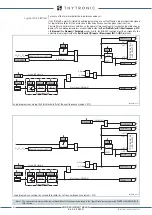
Consider a synchronous generator and relative step-up transformer connected to an external
network (fig. A). The electrical system can be simplified with two-generators model (fig. B):
• Synchronous generator is modeled with an ideal voltage generator (EG) in series
with direct transient reactance (Xd’)
• Step-up transformer is modeled with the relative short-circuit reactance (XT)
• Network is modeled through an ideal voltage generator (EN) in series with the equiva
lent network impedanceZ
N
.
Synchronous generator and step-up transformer resistive components are negligible, moreover
generator direct axis transient reactance is used since out of step is a relatively slow phenome-
non. EG, EN voltages and system reactances are also contemplated constant. For an in-depth
study it must be considered that external network impedance Z
N
varies in relation to different
scenarios, therefore system maximum and minimum impedance cases must be considered.
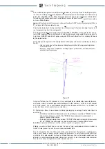
Out of step protection is based on impedance measurement obtained at generator ter-
minals. According to adopted model, the impedance measurement Z carried out by the
protection is obtained from the measurements of current I and voltage U, which can be
represented by equation (*).
XMR-D EQUIPMENT MANUAL
Ed. 2.9 - 02/2021


