


18
HA0165T Rev 4K Sept 2017
Chapter 4
times around the circle and, using the point on the circle where the power is highest,
detects the direction in which the fibers need to move to maximize the power coupling.
In order for the system to operate correctly in different applications, various software
settings (explained in Section 6.2.) may need to be adjusted. However, the default
settings should allow the NanoTrak to be operated in most cases, straight out of the
box without the need for a PC.
The following sections describe the front panel controls and how they can be used to
perform a typical series of operations.
4.2
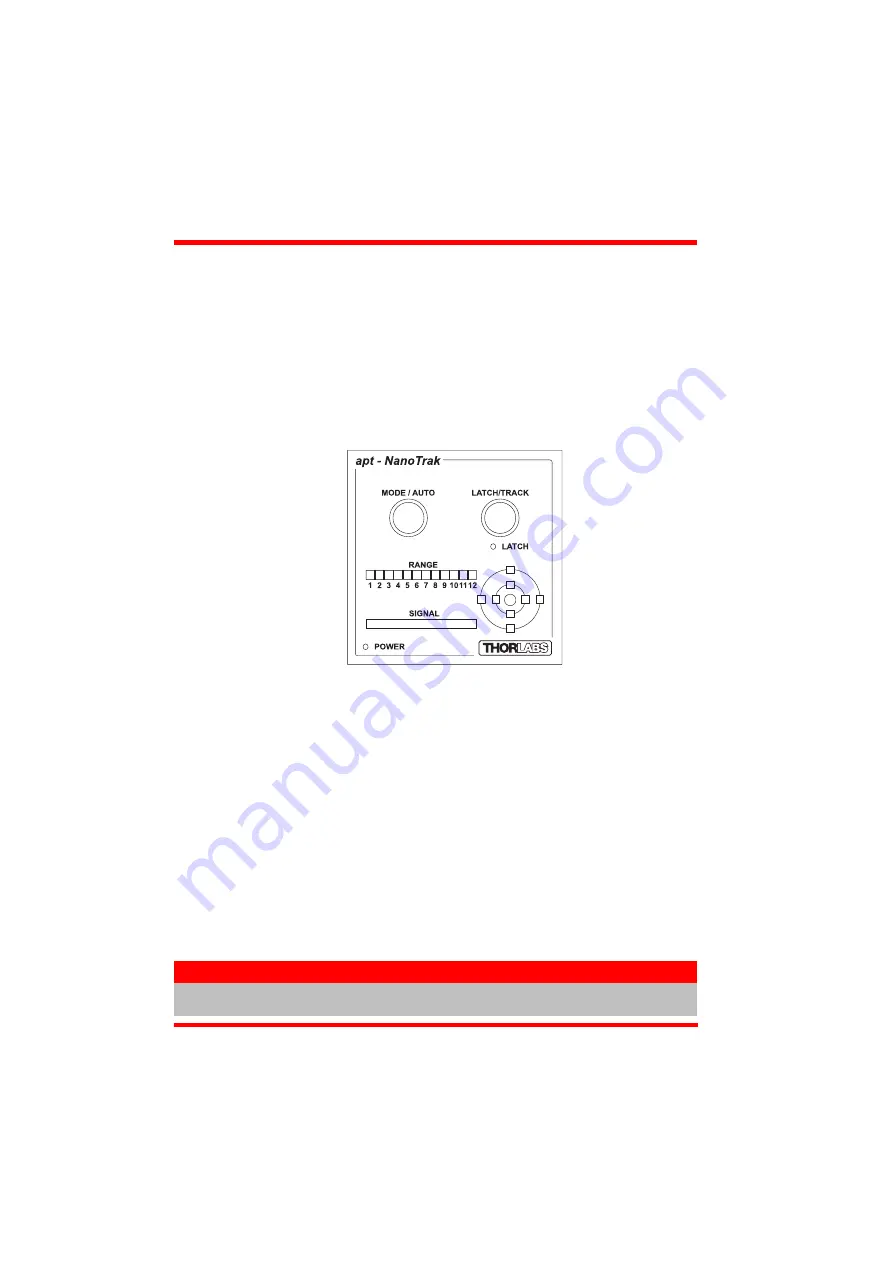
Control Panel Buttons and Indicators
Fig. 4.2 Panel Controls and Indicators
MODE/AUTO Button
- se lects and de-selects the ‘Auto Rang ing’ mode - see
LATCH/TRACK Button
- used to toggle between ‘LATCH’ and ‘TRACK’ modes of
operation - see Section 4.2.1.
LATCH LED
- lit when the unit is in LATCH mode - seeSection 4.2.1.
RANGE Bar
- displays the current range of the internal power meter. Available
ranges vary from 30 nanoamps (range 1) to 10 milliamp (range 12). Note that in
many practical a rrangements the l ower ranges may be un usable with typ ical
signal to noise ratios - see Section .
SIGNAL Bar -
the power level registered for the current range- see Section 4.3.2.
TARGET
- indicates the position of the output actuators in Y Z space - see Section
POWER LED
- lit when power is applied to the unit.
Note
The LATCH and the POWER LEDs will flash when the ‘Ident’ button is clicked on
the Software GUI panel - see Section 6.1. for further details.


