


10
MAX200 Series Motorized Microscopy Stages
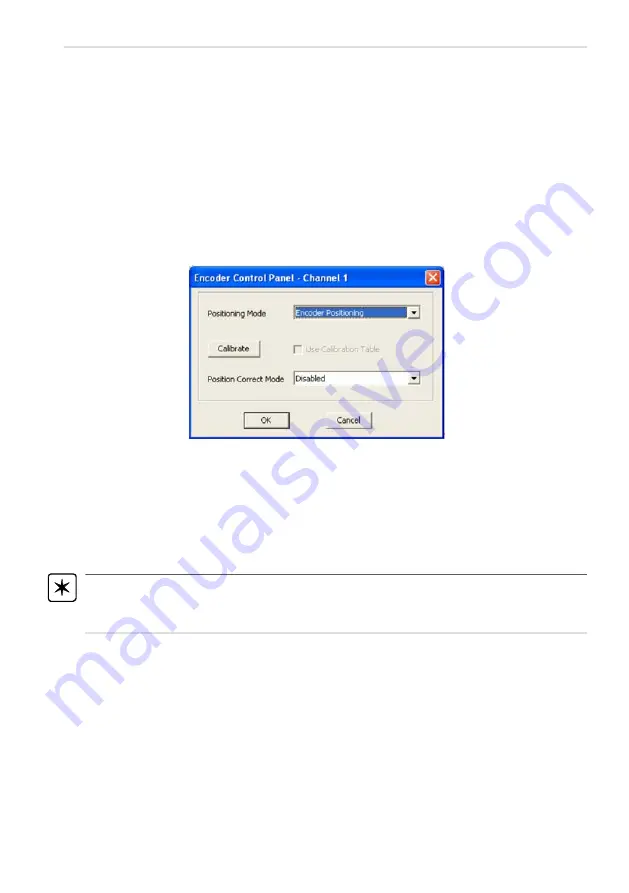
Positioning Mode
MicroStep Positioning
- By default the software is set to 'Microstep Positioning' mode. In
this mode, all position displays and motor moves are based on positions derived from the
internal microstep counters within the controller (i.e. are not based on the encoder count).
For example, the APT system can control to a resolution of 25600 microsteps per
revolution. For a stage or actuator with a 1 mm pitch lead screw, the controller will
generate 25600 microsteps to move 1 mm. To display position values, the software
converts the microstep count into a 'real world' position by dividing by 25600.
Encoder Positioning -
If 'Encoder Positioning' is selected, other controls on the panel
become available
.
In this mode, the position displays on the GUI panel, and all motor moves, are based
on positions derived from the encoder system fitted to the stage/actuator. So for
example, the encoders currently fitted to our stages are set to 10000 counts per mm
(i.e. 0.1micron per count). To move 1 mm, the controller will drive out the appropriate
number of microsteps to result in an encoder count change of 10000. To display
position values, the software will convert the encoder count into a 'real world' position
by dividing by 10000.
Note.
The positions values returned by the GetPosition and GetPositionEx methods are
derived from the microstep count in 'Microstep Positioning' mode and from the encoder
count in 'Encoder Positioning' mode - see the APT Server helpfile for more details.
3.4.2 Encoder Calibration Table
For a perfect 1mm pitch lead screw, a microstep count of 25600 would equate exactly
to an encoder count of 10000. However, due to lead screw pitch, non-linearity and
other cyclic errors, this is not achievable in the ‘real world’. It is the purpose of the
encoder feedback handling within the APT software to accommodate for this and
achieve the required encoder position (the more accurate position reading).
One way to accommodate for this lead screw non-linearity is for the system to acquire
a look up table of microstep count verses encoder count readings. Using this
'calibration' table the system is then able to adjust the microstep count required (to
drive the motor) to achieve the required encoder count.
Содержание MAX200
Страница 1: ...0 Microscopy Accessories Motorized X Y Stages Model Numbers MAX200 MAX201 MAX202 MAX203 ...
Страница 6: ...5 Chapter 2 Overview Fig 2 1 MAX200 stage with 96 hole well plate and mounted on a microscope ...
Страница 31: ...30 MAX200 Series Motorized Microscopy Stages www thorlabs com ...


