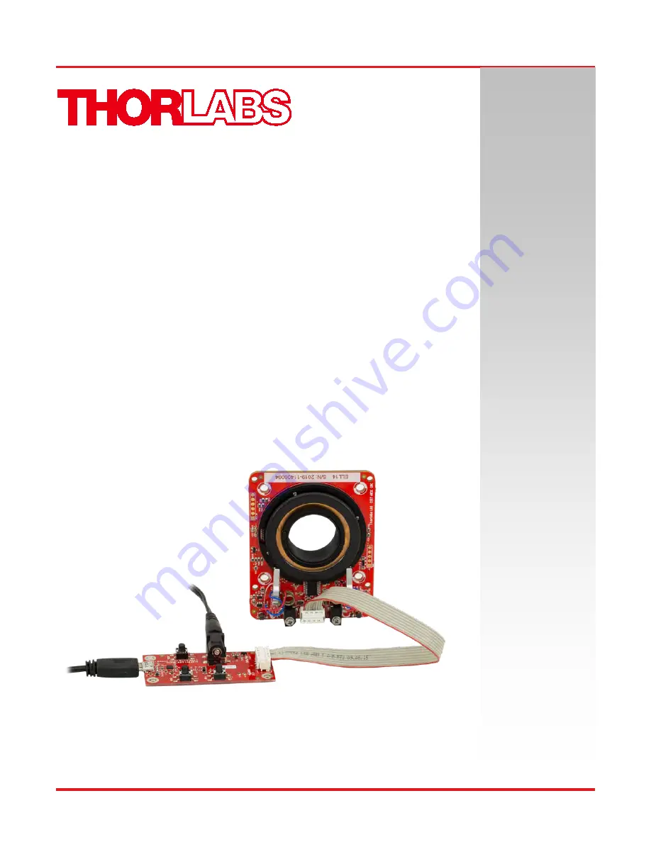
ELL14 Motorized SM1 Optic Rotator
ELL14 and ELL14K
Motorized SM1 Optics Rotator Kit
Operating Manual
Original Instructions
Страница 1: ...ELL14 Motorized SM1 Optic Rotator ELL14 and ELL14K Motorized SM1 Optics Rotator Kit Operating Manual Original Instructions...
Страница 2: ...nsation 6 4 2 1 Hand held Controller 8 4 2 2 Software Control 9 4 2 3 Communications Protocol 10 4 2 4 Connecting Multiple Devices 10 4 2 5 Controlling the Rotator Without the Handset 10 Chapter 5 Tro...
Страница 3: ...up to 359 99 again Furthermore the unit will not respond to requests for a move to a position greater than 359 99 and an error message will be generated It is designed for closed loop applications req...
Страница 4: ...ot specified by the manufacturer the protection provided by the equipment may be impaired In particular excessive moisture may impair operation The equipment is susceptible to damage from electrostati...
Страница 5: ...in explosive environments The unit is not designed for continuous operation Typical lifetime is 3 3 million switching operations which equates to 100 km of travel see Chapter 5 for more details Mounti...
Страница 6: ...s 3 Possible Mounting Hole Patterns The rotator is shipped with two SM1 retaining rings allowing SM1 optics to be fitted There are several options for mounting the rotator The unit can be mounted dire...
Страница 7: ...he rotator can be fitted to our ER series cage rods within a 30 mm cage system Figure 3 ELL14 Mounted in a 30 mm Cage System If combined with the SR series posts and the ELLA1 Adapter the unit can be...
Страница 8: ...switch ON A 5 V PSU is supplied with the ELL14K Caution Boot up the PC BEFORE connecting the USB cable DO NOT connect a powered ELL kit to a PC that is not powered up and running 2 Using the USB cabl...
Страница 9: ...ming and Jogging functionality can also be accessed by applying voltages to the digital lines on Connector J1 The modes of control are described in the following sections Caution In all modes the angu...
Страница 10: ...ternal 5V power supply The external PSU connector allows the rotator to be used in the absence of a PC with control being achieved via the handset buttons LED1 green is lit when power is applied to th...
Страница 11: ...r to the rotator unit 3 Connect the hand held controller to the 5V Power Supply and switch on 4 Connect the hand held controller to the PC USB port and wait for the drivers to be installed 5 Run the E...
Страница 12: ...e contained in the help file supplied with the software Connect the first device to the PC USB port then run the Elliptec software and load the device Change the address of the first device Connect th...
Страница 13: ...IN RX receive 3 3V TTL RS232 4 OUT In Motion open drain active low max 5mA 5 IN JOG Mode active low max 5V 6 IN BW Backward active low max 5V 7 IN FW Forward active low max 5V 8 PWR VCC 5V 10 800mA C...
Страница 14: ...ze the buildup of debris on the track and will prevent the motors digging a groove over the most used area of contact Typically a travel cycle should be performed every 10K operations Restoring Factor...
Страница 15: ...use an additional 5 V 1 A power supply and a USB connection Integrators should search for optimal frequency on every power up sequence commands s1 s2 see ELLx protocol document How do I restore the f...
Страница 16: ...time will depend on several factors e g load number of homing operations number of frequency searches etc and users must take into account all these factors when considering life time For example homi...
Страница 17: ...ace board When making a cable to operate multiple devices it is important to observe the correct pin orientation The following procedure offers guidance in making such a cable 1 Gather together the pa...
Страница 18: ...ke connection with the ribbon cable 4 If other connectors are required they should be fitted at this point Slide each connector onto the cable paying attention to the orientation as shown below then c...
Страница 19: ...to 5 5 V Typical Current Consumption During Movement 800 mA Standby Current 0 05 A Motor Type Elliptec Resonant Piezo 8 Conductor Ribbon Cable Length Supplied 250 mm 8 Conductor Ribbon Cable Length M...
Страница 20: ...gainst harmful interference when the equipment is operated in a commercial environment This equipment generates uses and can radiate radio frequency energy and if not installed and used in accordance...
Страница 21: ...lie bin logo see right were sold to and are currently owned by a company or institute within the EC and are not dissembled or contaminated Contact Thorlabs for more information Waste treatment is your...
Страница 22: ...www thorlabs com...