


© Thermoteknix Systems Ltd 2020
23
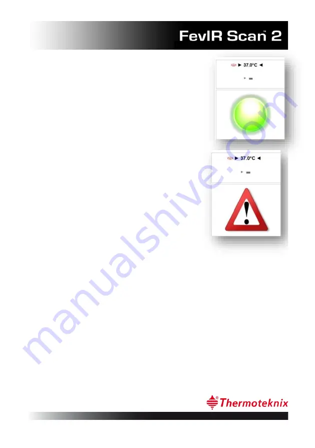
With the read-out temperature is the status display:
Green for normal condition
Red for an alarm condition
Or a warning triangle if the system is not ready. This
will be shown if the blackbody reference temperature
is not yet at its operating temperature and stable, or if
the FevIR Cam unit is not ready or stable.
When an alarm is triggered an audible alert is played
and a red circle drawn around the above alarm
threshold pixels. This helps the monitoring staff to
identify and isolate the potentially febrile subject for
further tests.
7.2
Defining the screening area: (Setup Menu, F7)
To ensure the correct operation of the system, the system operator must configure
two regions of the display.
The first region is to locate the calibration reference measurement tool over the
centre of the Calibration Reference Source. It is important that the Calibration
Reference Source unit is placed
outside
the intended area for Scanning. It is not
important whether the Calibration Reference Source is above or to the side of the
active Scanning area. Typically this will depend on whether the unit is ceiling or
floor mounted. It is essential that the view of the Calibration Reference Source
temperature from the position of the FevIR Cam cannot be obscured by persons
walking through the Scanning area. The calibration circle is drawn in yellow and
should be positioned so that it encloses the central heated area of the Calibration
Reference Source. This identifies the pixels that are at the calibration temperature
of the Calibration Reference Source and enables the system software combined with


