background image

Software control: Microscope Control

3-23

C O N F I D E N T I A L

 – limited rights 

User Manual


Revision A


Feb 2018

Toolbar 

The toolbar shown below the Menu bar is made up of functional graphical elements (icons, adjusters, etc.) linked 
to the most frequently used system controls.  

Note 

The default workspace is described here, for custom settings see corresponding sections of this manual. 

Rest the cursor over the icon for two seconds without clicking on it to see its 
explanatory tooltip. Right-clicking on some toolbar icons calls up a context 
menu with other functionality choices. For instance, a user can move directly 
to the 

Preferences

 setting (by clicking on the 

Edit

 item) or to change a mode 

of value depiction. 

Whenever a function is selected, the corresponding icon is highlighted 
(orange background) to indicate the function is active. 

Note 

If any icon represents a menu function, refer to the corresponding menu for its 
description. 

Undo / Redo 

The undo / redo buttons assist undoing / re-running the last actions. Actions used in history are 
accessible by clicking the down arrow. They can be re-used separately, or any continuous sequence of 
actions can be selected and re-used as a group. 

Note 

Some particular actions (alignments etc.) cannot be undone, and sometimes the system clears the history of actions. 

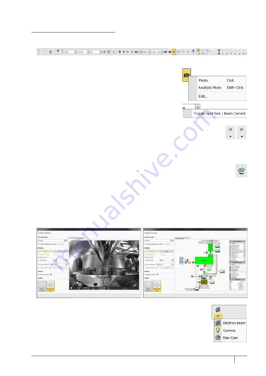
Sample exchange 

The window contains controls for sample exchanges, working conditions and start-up actions settings and 
information about the system vacuum status (see Chapter 5): 

The 

Working Folder

 for images storing with a possibility to 

Create Subfolders for Displays


Setting 

Sample Cleaning

 when pumping the chamber down 

Selecting Vacuum modes (

High Vacuum

 / 

Low Vacuum

) and associated parameters 

Take Nav-Cam Photo

 automatically 

Starting the sample chamber 

Purge

 process 

When processing a 

Magnetic Sample

,


ticking this check box prevents the Immersion lens and 

Compound Lens 

Filter

 to be switched on. 

Stage 

Holder

 selection  

Electron beam / Camera / Nav-Cam 

Selecting an item from the drop down list makes the display or single screen show the 

Electron Beam / Camera / Nav-Cam

 imaging with respect to the source, column, scanning, 

and detector settings. Only one is selected at any given time, but they can be operated 
independently for each display. 

Another way to change the beam for a particular imaging is clicking on the image databar 
beam icon. 

Содержание Apreo

Страница 1: ...Apreo User Operation Manual Revision A Mar 2018 ...

Страница 2: ...cated or disseminated for any third party without the express consent of Thermo Fisher Scientific Company Limited Rights Contractor Name Thermo Fisher Scientific Contractor Address 5350 NE Dawson Creek Drive Hillsboro Oregon 97124 USA The Government s rights to use modify reproduce release perform show or disclose these technical data are restricted to those rights specified in DFARS 252 227 7015 ...

Страница 3: ...stem 2 9 Vacuum status 2 10 Vacuum modes 2 11 Equipment 2 13 Detector types and application 2 13 Stages and accessories 2 14 Chapter 3 Software control Software interface elements 3 1 Icons 3 1 Tooltips 3 1 Pull down menus 3 1 Command buttons 3 2 Property editor 3 2 Edit boxes 3 2 Radio buttons Check boxes 3 2 Adjusters 3 3 2D controls 3 4 Modules 3 4 Dialogs 3 4 Tabs 3 4 Progress bars 3 4 xT micr...

Страница 4: ...r Alignments 4 17 Chapter 5 Operating Procedures Specimen Preparation and Handling 5 2 Needed Items 5 2 Natural Specimen 5 2 Coated Specimen 5 2 Mounting Specimen on Holder 5 2 Specimen Baking Unit 5 3 Microscope Control 5 6 Operation Pre Check 5 6 Inserting Exchanging Specimen 5 7 Selecting Vacuum Mode 5 7 Imaging Onscreen 5 8 Optimizing Imaging 5 9 Principles of SEM Imaging 5 9 Magnification 5 9...

Страница 5: ... 7 System Options Manual User Interface 7 2 Joystick 7 2 Uninterruptible Power Supply UPS 7 3 Optional Detectors 7 4 Optional detectors connection 7 4 Trinity Detector T3 7 4 Directional Gaseous Analytical Detector GAD 7 5 Directional Backscattered Detector DBS Angular Backscattered Detector ABS Concentric Backscattered Detector CBS 7 7 Retractable Annular Scanning Transmission Electron Microscopy...

Страница 6: ...F I D E N T I A L limited rights Feb 2018 RevisionA C iv CryoCleanerEC 7 30 Parts and Accessories 7 30 CryoCleaner Operation 7 31 Maintenance 7 32 Spare Vessel 7 32 Plasma Cleaner 7 33 Sample Cleaning Procedure 7 34 Chamber Cleaning 7 34 ...

Страница 7: ... 2 System control describes the system hardware interface elements vacuum system system states equipment 3 Software control describes the interface that sets and controls system operation gives the function of each tool menu item and control page 4 Alignments explains how to align the equipment to achieve the optimal performance 5 Operating procedures gives procedures for how to use the system s f...

Страница 8: ...es with the electron beam during navigation without erosion System performance The main instrument components used for imaging of the samples are Electron source The beam of electrons particles is emitted within a small spatial volume with a small angular spread and selectable energy Lens system The beam enters the lens system consisting of several electromagnetic or electrostatic lenses and exits...

Страница 9: ...d with all scanning electron microscopes Low Vacuum LoVac mode In the gaseous mode the electron column is under lower pressure than the specimen chamber This mode can use water vapors from a built in water reservoir or an auxiliary gas that is supplied by a user and connected to the gas inlet provided for this purpose Observation of outgassing or highly charging materials can be made using this mo...

Страница 10: ...cimen Gas injection system GIS Multiple GIS option can be installed for material deposition in conjunction with electron beam pattern definition Electron beam induced deposition offers the advantage of not sputtering of the deposited material Several GIS chemistries can be installed on the instrument depending on system configuration This self contained apparatus allows the material to be containe...

Страница 11: ...er the protection provided by the equipment may be impaired Mains power must be connected to a grounded socket that is visible and easily accessible A user must not disconnect any parts of the equipment or connect any equipment not approved in this manual or in the Apreo User safety manual All power and external equipment connectors should be covered by stoppers part of delivery when not used Othe...

Страница 12: ...he stem must be significantly different from a previous password and shouldn t contain a complete dictionary word or user name must contain at least one character from each of these character groups Uppercase letter Lowercase letter Number Symbol etc Hardware The system is computer controlled As such it has a Microscope Computer that must be turned on use the power button on the PC to operate the ...

Страница 13: ...against power failures in the sense that the different components of the system are not likely to be damaged However a power failure is never good for the system It might affect the ultrahigh vacuum levels of the columns and the overall stability of the system Take sufficient measures to avoid power failures If a power failure occurs while the instrument is completely operational the microscope en...

Страница 14: ... switch labeled Main switch S1 at the cabinet back which is placed at the very left side of the row of three or disconnect the power cord labeled Main input 230 VAC FIGURE 2 3 Mains switch board If this is not easily accessible 3 Turn off the mains wall switch if present and or disconnect the mains plug from the mains socket WA R N I N G The microscope console water chiller option separate device ...

Страница 15: ...s procedure 1 Push the amber Power button on the Microscope console panel it changes to green a 2 Switch on the Microscope computer The operating system b Windows 7 loads and shows the appropriate icons on the monitor desktop 3 Double click the xT microscope Server icon to start the software all visible LED s should be green Initialized 4 Click the Start button to start the server Wait until all e...

Страница 16: ...he system remains on with the vacuum system in operation but typically the emitter and accelerating voltage remain off The system starts with the setting last in use when the Microscope Control software was closed This allows quick resumption of daily operation Overnight and Standby In the Full operation state all microscope equipment and accessories are in use or are ready to use When leaving the...

Страница 17: ...ain window appears behind the UI Log On dialog Note This step can take place automatically if the Advanced Autorun UI check box has been ticked Now the system is in the Overnight state To proceed to the Full operation state follow this procedure 5 Enter your Username and a Password b 6 Click on the Column module Beam On button to start the beam The source awaking progress bar indicates the actual ...

Страница 18: ...es and the console the green power button on the microscope front control panel changes to amber g 5 Shut down Windows 7 and switch off the monitor 6 If needed disconnect the power cord and any other input output used h Note f Switching off the console when the Emitter is on is not optimal for the emitter it may deteriorate its filament lifetime g The system can be left in this state if electrical...

Страница 19: ...ays under high vacuum The specimen chamber is at the pressure required for the given state Pump Vent or mode HiVac LoVac Note When the LoVac mode is chosen the ChIV is closed All valve and pump operations are fully automatic FIGURE 2 4 Apreo high vacuum Apreo low vacuum Vacuum system AGV Auxiliary Gass Valve BPV By Pass Valve BG Buffer Gauge BV Buffer Valve CIV Column Isolation Valve ChEV Chamber ...

Страница 20: ...em immediately starts to pump to the actually selected vacuum mode Vent button When the Vent button is clicked and the status is Pumped the confirmation dialog appears After confirmation the system switches off the detector voltages high voltage supplies vacuum pumps and uses the appropriate valves to vent the system with the use of the dry nitrogen brought to the Nitrogen Inlet Nitrogen is recomm...

Страница 21: ...wever the system will not abort the pump sequence Pressure The Chamber Pressure adjuster is used to set and show the target chamber pressure Pascal Torr or Millibar units are available and can be selected in the Preferences dialogue Units tab When the system is in LoVac mode and the Chamber Pressure value is changed the pressure automatically changes to the new value When the system is in any othe...

Страница 22: ... the Auxiliary gas and Nitrogen inlets is 10 kPa 0 1 bar The Nitrogen inlet is used only for venting the chamber with air or preferably with nitrogen When using a particular pressure limiting aperture there are pressure limits for different gasses C a u t i o n The system doesn t watch the limits and higher overpressure especially for gasses not listed set by a user could switch off the emitter In...

Страница 23: ...ety interlock is activated it is necessary to confirm switching the detector voltage on after pumping the system Table 2 2 Apreo detectors list Detector name Tag Vacuum mode Detected signal Note Everhart Thornley ETD HiVac SE tunable energy BSE S T1 T1 HiVac LoVac SE for OptiPlan and Immersion Use cases S T2 T2 HiVac LoVac SE for OptiPlan and Immersion Use cases S Low Vacuum LVD LoVac SE S CCD cam...

Страница 24: ...System control Equipment 2 14 User Manual C O N F I D E N T I A L limited rights Feb 2018 RevisionA FIGURE 2 5 Safety interlock message ...

Страница 25: ...are controlled an integrated part of the Microscope Control software Stage positions are shown on the screen FIGURE 2 6 110 110 mm chamber Multipurpose stub holder The holder contains 18 horizontal and three pre tilted positions for 12 5 mm stubs Horizontal and pre tilted positions for the STEM row holder are also included together with a sample clamp and a Faraday clamp All positions are marked f...

Страница 26: ...men the magnification may need to be reduced so as to not lose the feature of interest from the screen FIGURE 2 7 Stage movement schema C a u t i o n The positive Z value direction depends on the Link Z to FWD status see Chapter 5 C a u t i o n If the maximum sample size is near the limit stage tilt can be limited Beware of hitting the objective pole piece Table 2 3 Stage features and limits Item ...

Страница 27: ...lar function cyclic changeover of choices setting the default parameters etc There are also some informational icons in the status bar such as those that indicate a particular system status Tooltips The Tooltips functionality activates when the cursor is left over an item on the user interface for more than two seconds A short explanation of the item appears until the cursor is moved away from it ...

Страница 28: ...ommon ones which are typically used in dialogs are OK button applies all changes made in the dialog and closes it Finish button saves new settings ends the procedure and closes the dialog Save button saves new settings at that point without closing the dialog Apply button saves and applies new settings at that point without closing the dialog Cancel button discards all changes made from the last s...

Страница 29: ...ider Mode Non linear Slider checked the slider has an exponential response the farther from the center the adjuster button is pulled the larger the relative change The adjuster button always snaps back to the center of the slider but the small bar under the slider corresponds to the actual parameter value It is possible to increase decrease the Slider Mouse Speed sensitivity by dragging the contex...

Страница 30: ... remembered automatically during the relevant 2D control use These remembered values are used to estimate new values that have not yet been remembered The menu may contain fewer functions or some other functions that are available for that particular parameter Selecting the corresponding menu item activates the function Modules Modules visually combine various software elements that are related in...

Страница 31: ...e Server Microscope Control software service Clicking on the Start Stop button starts stops xT microscope Server services If the UI is running the Stop button first closes it Clicking on the Start UI Stop UI button starts stops the UI Clicking on the Show UI Hide UI button shows hides the UI main window Clicking on the Standby button closes the UI stops the xT microscope Server services and brings...

Страница 32: ... icons for the most frequently used microscope controls 4 Imaging area also shows the adjustable Databar 5 Control pages set of modules 6 Modules microscope and imaging control elements 7 Preferences dialog presetting of operating conditions Workspace customization It is possible to change the UI layout by right clicking any free toolbar or sidepane pages area and selecting the Customize item A us...

Страница 33: ...ng a new item from the Toolbar tab to the toolbar area adds it to the layout FIGURE 3 3 Toolbar customization Sidepane Pages customization Selecting the Sidepane tab adds a red border to the pages area By clicking dragging any module that module can be moved to a new position within the pages area dragging it out from the pages area to the customization window eliminates it from the layout Clickin...

Страница 34: ...ortcuts customization It is possible to customize the factory shortcuts within the Kayboard tab To change the factory settings search for a desired functionality enter a New Shortcut to the edit field and click the Assign button To revert to the factory settings click the Default button FIGURE 3 5 Shortcuts customization ...

Страница 35: ... administrative functions Open shows a standard dialog for opening images previously stored to media Supported digital file formats are TIF8 16 24 JPG and BMP see Chapter 5 The dialog shows by default the location path last used to open or save files from the UI Save Ctrl S saves the image using the format location and base name set by the last used Save As function in that display An incremental ...

Страница 36: ...iles active display parameters Beam type Detector type Detector Mode Detector contrast brightness Digital Contrast Digital Brightness parameters System Parameters par files A wide range of selected actual microscope settings are stored including most of those mentioned above When importing them back only the selected settings are loaded Log Off user name logs off the present User and provides the ...

Страница 37: ...ing to the previous state Shift clicking on the toolbar pause icon pauses activates all displays at once if the detectors in different displays are mutually compatible Snapshot F4 Photo F2 activates a preset scan see the Preferences Scanning section to acquire an image Active Preset Snapshot Ctrl F2 This item starts acquiring a snapshot with parameters corresponding to the active highlighted by or...

Страница 38: ...ning line sawtooth signal is synchronized with the mains AC oscillation This greatly diminishes blurring and jittering of the electron imaging resulting in smooth image edges at higher magnifications and slow scan conditions Line Integration With this function each line scan is repeated several times from 2 to 255 before proceeding to the next line Signal data collected from these passes are integ...

Страница 39: ...he stage movements and is solely a scan coil electrode function used to orient the imaging relative to a specimen feature and or detector direction A non zero scan rotation is indicated by an icon in the Status bar Preferences Ctrl Alt S Clicking this item opens the Preferences dialog Scanning item see further Beam menu opens the Beam menu functions SEM Aperture This item is not available for the ...

Страница 40: ...ctual patterning is stopped and the procedure continues with the next pattern if present Autostart Real Time Monitor When selected it releases the pause function for the display with patterns enabling an automatic start of the real time monitoring RTM of the milling process Live RTM after Snapshot After acquiring a snapshot the RTM feature continues automatically Blackout Pattern Area for RTM In c...

Страница 41: ...e maximal value during the Get function the point to point stage movement and corrects the imaging position with a stage movement Home Stage Shift F3 starts the procedure that moves all motorized axes to their hardware limits and ensures that the physical stage position agrees with the coordinates readout During the home stage procedure the Stage Homing dialog shows its progress The stage axes are...

Страница 42: ...w this message again check box disables this notice permanently Enable Z Tilt Map Some movements of the tilted stage are not safe because of a possible collision with the final lens The table not user editable with pairs of values indicates the maximum safe Tilt angle for a certain Z value when linked It can be used to guarantee safe usage of the stage tilt restriction for flat samples only and wh...

Страница 43: ...1 activates the automatic procedure to correct any astigmatism Note Auto functions are only enabled during live imaging Auto Lens Alignment activates the automatic Lens Alignment functionality see above Set HFW Ctrl H enables setting the desired Horizontal Field Width i e the width of the scanned area This is an alternative to setting the magnification Display Saturation Shift F11 shows signal cli...

Страница 44: ...trol Microscope Control 3 18 User Manual C O N F I D E N T I A L limited rights Feb 2018 RevisionA FIGURE 3 8 Application status Preferences Ctrl O letter Clicking this item opens the Preferences dialog see further ...

Страница 45: ...a 10 mm label in all optical imaging displays to help the user with positioning a sample to a correct working distance and with the first focusing Only a Supervisor is allowed to change the marker position by double clicking on a new position Crosshair Cursor shows the cursor as a rectangular cross through the entire display Working Distance Indicator Checking this item displays the working distan...

Страница 46: ...n the secondary monitor FIGURE 3 9 Large image window Large Image Window Configuration Here one can select whether to show the Active display or any selected display Activating the Use Single Image Size option sets the imaging window size corresponding to the Single Image mode size These options are also available in the bottom right corner of the large image window Remote Mode When ticked this fe...

Страница 47: ...mode Ctrl F5 toggles Large Image Window mode On Off Shift F5 toggles Center Cross On Off F6 pauses releases scanning Shift F6 toggles Alignment rectangle On Off F7 toggles Reduced Area On Off Ctrl F7 starts Image Post Processing F8 starts Degauss procedure Shift F9 starts Auto Contrast and Brightness procedure in all active displays Ctrl F11 starts Auto Focus Auto Stigmator procedure Shift F11 tog...

Страница 48: ...8 RevisionA User guidance This pop up window contains detailed instructions about some complex procedures and or settings FIGURE 3 12 User Guidance About Microscope Control The window containing information about the product version is shown It automatically disappears after the first click anywhere ...

Страница 49: ... arrow They can be re used separately or any continuous sequence of actions can be selected and re used as a group Note Some particular actions alignments etc cannot be undone and sometimes the system clears the history of actions Sample exchange The window contains controls for sample exchanges working conditions and start up actions settings and information about the system vacuum status see Cha...

Страница 50: ... Spot is defined as the actual electron beam diameter on the specimen surface It is expressed by a relative number The optional way representable in the toolbar to express the Spot is the electron beam current value see the Preferences dialog General section Beam current control item Both physical quantities are related The electron beam current shown in the toolbar list box and optionally in the ...

Страница 51: ...a freely drawn line Pattern presets By default there are 6 empty toolbar Pattern presets labeled p Any pattern preset can be assigned to an individual ptf file with all patterning parameters exported via the File menu Export Patterns item Clicking on any pattern preset loads its parameters from this file and corresponding patterns are drawn in the active display To start patterning under loaded co...

Страница 52: ...g the Scan menu Active Preset Snapshot Ctrl F2 item Clicking on the Snapshot Multiple Snapshot item starts snapshot acquisition from active all compatible displays Clicking on the Update with Current Settings item updates the selected Scanning preset with the actual scanning settings Clicking on the Edit item opens the selected Scanning preset property editor It is also possible to use the toolbar...

Страница 53: ...unctions are available over its area Electron imaging incl External and Mix focus astigmatism correction Beam Shift magnification change coarse fine zoom in out Contrast Brightness lens alignment Scan Compucentric Rotation XY move get or track mode Optical imaging 10 mm Marker placement Compucentric Rotation Z move track Tilt Working distance indicator Optical imaging is automatically activated if...

Страница 54: ... is included in the databar right click on any display databar and click on drag the desired Available Item to the Visible Items field Items can be placed in any order by dragging items up down within the list They expand or contract automatically to fit the display width as long as there is enough room This influences all displays with the same beam FIGURE 3 14 Databar configuration Image propert...

Страница 55: ...he electron current leaving the source Electron Source Pressure pressure in the corresponding vacuum system section Clock can be shown at the bottom right window corner Messages Application Status incoming notices can be shown The system conditions are shown by means of the icons When you hover the mouse over any icon a corresponding tooltip appears with either the actual status of the parameter s...

Страница 56: ...ctual beam type is indicated by the corresponding icon at the right hand side of the module 1 Vacuum module This module is used to control the pressure in the specimen chamber Clicking on the Pump button starts the pump down procedure for the specimen chamber and the column The system allows switching the accelerating voltage on only when the chamber is sufficiently evacuated Clicking on the Vent ...

Страница 57: ...lens is to focus the primary electron beam to the sample However independent control of these three lenses together with continuous control of the immersion lens enables to filter back scattered BS electrons reaching the T1 detector The compound lens filter behaves as a chromatic sensitive lens which focuses the low energy BS electrons into the aperture of the annular T1 detector The high energy B...

Страница 58: ...t value to zero and moves the stage to compensate for the resulting imaging shift same as the Stage menu Beam Shift Reset function 6 Beam Deceleration module In the Beam Deceleration mode option a negative potential Stage Bias is applied to the stage which influences both primary and detected electrons This functionality is standard for biases ranging from 50 V to 50 V There is an option for biase...

Страница 59: ... across the sample surface Note The stage movement can be aborted by pressing the keyboard Esc key Don t hesitate to do so if you are not sure that the initiated movement is safe 10 Stage Z module This module enables slowly moving the stage in the Z axis direction The more the slider is pushed to the each side the faster the stage motion will be Clicking on the slider bar moves the stage by small ...

Страница 60: ...ws the Overall Current pattern Progress over time of the actual patterning 14 Properties module Some features Measurements Annotations Patterns require an individual set of parameters which are editable within this module by clicking on the edit field or the down arrow to choose a value 16 Digital Zoom module This procedure takes place in computer memory only and helps navigate across the enlarged...

Страница 61: ...he LUT Color Process tab its background changes to orange The digital processing can be applied to any live paused or loaded image including an optical one see Chapter 5 FIGURE 3 16 Enhanced image module 18 Direct Adjustments module This control page serves for fine tuning of beam geometry to achieve the best focus and brightness see Chapter 5 FIGURE 3 17 Direct Adjustments module 19 Use Case modu...

Страница 62: ...dialog Detector settings contains information in the format detector detector mode Particular settings for a detector custom mode are not supported in column presets Mix detector cannot be used for a column preset Right clicking on any preset button calls up the context menu Clicking on Edit opens the selected preset button properties for editing with sections for Column Beam Deceleration Detector...

Страница 63: ...ins a list of Alignment procedures available for the actual user level User Supervisor or Service C a u t i o n A user must understand the procedures at the appropriate level before proceeding with any adjustment Improper alignments can make the system difficult to use Note Some alignment modules may have some features distributed differently than others but their functionality is the same unless ...

Страница 64: ...required section opens it and allows changing and presetting conditions for a group of related functions The items changed remain valid for a specific user when logged on next time Some of the preference controls are beam dependent In this case the actual beam type is indicated by its corresponding icon and controls change accordingly Movie For a detailed description see Chapter 5 Units allow a us...

Страница 65: ...tual SEM conditions are not shown in the toolbar Magnification list box Note Alternatively magnification could be shown as the Horizontal Field Width see the Preferences dialog General section Image dimensions control item Stage Tilt and Rotation presets can be set in Absolute or Relative values Pressure list can be changed to hold specific values frequently used in the Low Vacuum ESEM mode within...

Страница 66: ...on Yes No corrects imaging drifting when the integration filter is active When activated the text below the blinking pause icon within the display notifies a user Continuous Scan Yes No when set to yes and the Snapshot Photo function is started during scanning the scanning finishes and the resulting image is acquired according to the preset This functionality requires the same scanning conditions ...

Страница 67: ...ting databar magnification representation behavior Clicking the radio button activates the correction technique Real screen size the imaging pixel width is handled Active view The databar magnification value depends on whether the Single or Quad Image mode is selected It is shown in the image databar and stored printed with an icon representing the Single Quad Image mode Single image display mode ...

Страница 68: ...ic all purging parameters are set automatically according to the mounted Low Vacuum detector Cone Custom custom settings see below are used Purge Settings area contains following Custom settings and controls Minimum Pressure Maximum Pressure Number of cycles Sets the above three parameters to the desired values for the procedure The Purge button enables starting to purge manually using the actual ...

Страница 69: ...ng page Property module Application item by checking the check box next to an application name FIGURE 3 23 Pattern Applications preferences The Default button sets the original settings Sensitivity The preset sliders control the sensitivity of the Manual User Interface MUI option FIGURE 3 24 Sensitivity preferences All MUI controls are represented except Magnification The Default button sets the o...

Страница 70: ... Alignments It is possible to enable visibility of alignments in the Alignments page Alignments list by checking the Visible check box next to an alignment name FIGURE 3 25 Alignments preferences Sounds section Use the Sounds section to set system sound notices for selected tasks FIGURE 3 26 Sounds preferences ...

Страница 71: ...ng to any other Preferences section FIGURE 3 27 General preferences Each item in General Preferences is represented by a single line shown in the property editor Clicking on the corresponding Value shows a drop down list with the settings available for that item Note Some of the items are model dependent and some are intended for options To make navigation among the number of preferences easier th...

Страница 72: ...e of a toolbar icon and Yes is set the patterning page activates automatically Image and Graphics Restart average filter when magnification changes Restart average filter when scan rotation changes Restart average filter when beam shift changes Restart average filter when stage moves No Yes These items enable choosing whether imaging averaging should be restarted when the indicated parameter chang...

Страница 73: ...ons Blank E beam during long stage moves Yes No Specifies whether the electron beam should be automatically blanked during long software controlled stage movements This may protect extremely sensitive samples from exposure to the beam in undesired areas Delete image data when user logs off Yes No If Yes any live and or paused imaging in all displays is deleted when user logs off Unpause CCD camera...

Страница 74: ...7 and the xT microscope Server Microscope Control software Accounts control You can start the software by clicking the Thermo Scientific menu Service Tools Account Manager icon This brings up the Log On dialog box containing User and Password text fields for entering the account manager For the first time log on with the Supervisor Supervisor credentials the application window appears The Supervis...

Страница 75: ...ion for a selected highlighted account Log on logs on a new user an actual user is logged out Exit exits the application Change Password Description sets a new password account description Reset User Settings restores user account setting to the factory default Copy User Settings select a user account from which settings are copied Add Create Supervisor Remove Account Supervisor enter information ...

Страница 76: ...gs Electron beam settings HV current HFW Dwell resolution position for each beam in full frame reduced area line and spot modes Detector settings bias voltages etc Preferences Workspace toolbar side pan pages keyboard short cuts Stored settings for each display Active beam electron optical Image save file path Image save settings databar or overlays included Stored settings for each beam in each d...

Страница 77: ...ght Ctrl click on drag controls the detector contrast brightness by dragging the mouse left right up down Shift click on drag hand cursor activates the Beam Shift Double click on Electron Imaging Get mode moves a point to the display center Optical Imaging places 10 mm marker Right click on drag 2 ended arrow cursor focuses by dragging the mouse left right Ctrl right click on drag 4 ended arrow cu...

Страница 78: ...er accelerator key can subsequently be selected Alt Tab switches between running applications each time the Tab key is hit while holding the Alt key a pointer jumps to another application icon Releasing the Alt key at any time makes the application just listed become focused Alt F4 closes focused the application or the Windows operating system Del ete deletes a selection texts or graphics Ctrl A s...

Страница 79: ...gles Single Quad Image mode Ctrl F5 toggles Large Image Window mode On Off Shift F5 toggles Center Cross On Off F6 pauses releases scanning Shift F6 toggles Alignment rectangle On Off F7 toggles Reduced Area On Off Ctrl F7 starts the Image Post Processing procedure F8 starts the Degauss procedure Shift F9 starts the Auto Contrast Brightness procedure in all live displays F11 starts the Auto Focus ...

Страница 80: ...Ctrl Shift sets one step faster fastest scanning Ctrl Shift Tab activates displays stepwise backward Ctrl Page Up Down switches within Control pages stepwise Ctrl 1 2 3 letter keypad selects the particular page the number corresponds to the page icon sequence Ctrl keypad increases decreases the magnification 2 Digital Zoom keypad rounds off the magnification HFW to a nearest round value Ctrl Alt a...

Страница 81: ... for all alignment procedures when available Start button starts the procedure and proceeds with subsequent dialogs End button moves a user to the last step after clicking on the Next button to enable finishing the alignment procedure Finish button saves new settings ends the procedure and closes the dialog Save button saves new settings at that point without closing the dialog OK button applies a...

Страница 82: ...tilities Stage Rotation Center sets the stage rotation center for the compucentric rotation Others 154 Water Bottle Venting Enables venting the water bottle to allow refilling it External Plasma Cleaning Plasma Cleaning Enables chamber plasma cleaning and sets the duration of the specimen plasma cleaning Vacuum Actions set of utilities Start Stop IGPs enables starting stopping vacuum pumps in case...

Страница 83: ...before proceeding with any alignment If you have any e beam alignment procedure selected and you want to select another one you must Finish or Cancel any actually opened procedure first To start the alignment procedure or to stop one in progress right click on the red circle and select the required action Start Stop variable from the context menu A confirmation dialog is shown When interrupting an...

Страница 84: ...has never run or that it failed to do anything meaningful the difference between these two is not important Reliable The result is trusted by the automatic procedure or a user has passed the alignment step manually Unreliable The automatic procedure has done meaningful work but cannot decide whether the obtained result can be trusted This suggests reviewing the result manually Out of range The aut...

Страница 85: ...D E N T I A L limited rights UserManual Revision A Feb 2018 E column Emitter Startup This procedure enables electron source switching On Off In cases of emergency shut down it allows starting the IGP s Ion Getter Pump to pump the electron source space ...

Страница 86: ...s Feb 2018 RevisionA Magnification Correction This utility is intended to enhance factory calibration accuracy under particular user selectable conditions Note Switch the Beam menu Magnification Correction item on only for calibrated conditions Otherwise it can worsen magnification accuracy ...

Страница 87: ...e Selection 4 7 C O N F I D E N T I A L limited rights UserManual Revision A Feb 2018 E Column Aperture Selection The aperture holes edges cleanliness is very important If an imaging is poor try to select an alternative aperture ...

Страница 88: ...8 RevisionA E Column Preventive Maintenance Source Tilt Shift Fast This user level alignment ensures centering the electron beam in the column It should be executed regularly on a weekly basis It takes around 15 to 20 minutes If it is not successful run the supervisor level alignment Source DPA Tilt Shift ...

Страница 89: ...al Revision A Feb 2018 E Column Supervisor Alignments This set of alignments enables the following actions Sample Alignment First alignment of this set allows a user to find appropriate sample locations within the sample holder and save them These positions are used in the following procedures ...

Страница 90: ...upervisor Alignments 4 10 User Manual C O N F I D E N T I A L limited rights Feb 2018 RevisionA Aperture Alignment This procedure mechanically centers different electron apertures on the aperture strip module in the column ...

Страница 91: ...urs and should be executed when necessary It centers the electron beam in the column using three variables DPA Differential Pumping Aperture separates the high vacuum column part from the chamber vacuum centers the electron beam to pass through the column without any cutoff Tilt centers the beam on the optical axis Shift centers the beam on the center of the final lens ...

Страница 92: ...r Manual C O N F I D E N T I A L limited rights Feb 2018 RevisionA Image Shift Correct imaging shift when changing the accelerating voltage and or Use case Stigmator Alignment Correct imaging shift when changing the accelerating voltage and or Use case ...

Страница 93: ...Alignments E Column LoVac Alignments 4 13 C O N F I D E N T I A L limited rights UserManual Revision A Feb 2018 E Column LoVac Alignments This set of alignments enables the following actions ...

Страница 94: ...age module R value the stage moves around its mechanical center In some cases this is not desired because a rotation around the field of view center would be more useful use this alignment to set this situation Make sure the stage tilt is zero during alignment The magnification should be from 500 to 2 000 and the sample should have a well recognizable feature at least 10 mm from the center to impr...

Страница 95: ...Alignments 154 Water Bottle Venting 4 15 C O N F I D E N T I A L limited rights UserManual Revision A Feb 2018 154 Water Bottle Venting See Chapter 6 ...

Страница 96: ...leaning are pumped away and the following plasma cleaning is more effective Adjust the Cycle duration Clean cycles and Pumping time between cycles Note If there is an external Evactron plasma cleaner follow the External Plasma Cleaning alignment instructions and the Evactron user manual WA R N I N G Do not use Chamber cleaning when the EDS WDS EBSD system is mounted If you need to clean the system...

Страница 97: ...Alignments Vacuum Actions 4 17 C O N F I D E N T I A L limited rights UserManual Revision A Feb 2018 Vacuum Actions Start Stop IGP s Pump Vent Actions Pump Buffer ...

Страница 98: ... Feb 2018 RevisionA GIS Alignment option The GIS Port area shows the particular GIS controls Change the target crucible temperature for a particular GIS by the GIS Port Temperature C slider Click on any of the GIS Port Reset Lifetime buttons to reset the corresponding GIS lifetime records ...

Страница 99: ... covered Specimen preparation and handling Optimizing imaging Standard detectors Capturing and handling a Single image Recording movies saving multiple images Stage control Measurement and annotation functions Patterning milling C a u t i o n These procedures assume you are familiar with the xT microscope Server and Microscope Control software see Chapter 3 which are necessary to start and operate...

Страница 100: ...uccessful imaging rough surfaced specimens must be evenly coated from every direction Biological cloth and powder specimens may require carbon or other conductive painting on portions of the specimen that are hard to coat Coating makes the imaging sharper and reduces beam penetration It may mask elements of interest for X ray analysis thus the use of carbon for geological and biological specimens ...

Страница 101: ...tructions provided with this unit can result in bodily injury and property damage from hazards of fire or burn WA R N I N G Do not leave the unit unattended when it is ON Do not open the lid when the unit is ON Be extremely careful to avoid bodily injuries from burning When opening closing the lid always use the plastic knobs otherwise there is risk of burning When replacing the halogen bulb alway...

Страница 102: ... than 250 C WA R N I N G Do not look directly at the operating bulb for any period of time Doing so may cause serious eye injury Risk of burning For support tray manipulation sample loading for instance always use the special tool delivered Never touch the inner surface of the baking unit including the trays and specimens with bare hands or hands in gloves FIGURE 5 3 Support tray Handling tool Rem...

Страница 103: ...an be cleaned in an ultrasonic bath C a u t i o n Do not clean the Baking unit in the ultrasonic bath Halogen bulb replacement WA R N I N G The bulb operates at extremely high temperatures that can cause serious physical injuries and property damage Never touch bulb when it is on or soon after it has been turned off as it is hot and may cause serious burns When replacing the halogen bulb always we...

Страница 104: ...high voltage for conductors high resolution composite info BSE X ray Examples biological samples HV 1 10 kV metal samples HV 1 30 kV Beam Current Spot size 100 pA at 30 kV High Vacuum Low Vacuum 5 6 Scan rate High Vacuum fast scan dwell time 0 1 0 3 µs Low Vacuum slow scan dwell time about 3 µs Working Distance FWD Set the highest specimen point to approximately 10 mm yellow mark in an optical ima...

Страница 105: ...lso shown within the informational window by clicking on the toolbar icon Selecting Vacuum Mode When a specimen and appropriate detector s are installed correctly continue the procedure see above 4 Check the High Vacuum module Low Vacuum or High Vacuum mode radio button For the Low Vacuum mode select the appropriate gas from the drop down list and the target Chamber Pressure to pump the system to ...

Страница 106: ... hand Store it attached to the mounting tool in a clean plastic bag 8 Select an appropriate cone and click the Vacuum module Pump button While pumping choose the highest specimen point and bring it to the 10 mm Working Distance yellow line in optical display Imaging Onscreen Continue the procedure 9 When the vacuum status is PUMPED see the status bar click on the Column module Beam On button to ra...

Страница 107: ...emory location At any time after the beam scan the computer can access the data and process it to change its properties or use it to generate an image Magnification Magnification is calculated as the shown dimension L divided by the sample scanned dimension l If the observed sample area is made smaller while the monitor size remains constant the magnification increases At low magnification one get...

Страница 108: ...ellow horizontal lines placed over the display indicate white top line gray middle line and black bottom line levels The oscillogram signal amplitude central position reflects the contrast brightness of the line just scanned If the oscillogram is cut by the bottom top line the signal level is clipped in black white This should be avoided because imaging details are lost in the clipped areas Tuning...

Страница 109: ...al imaging blur X and Y rays are not focused to the same plane It is best seen on the edges of observed sample structures Stigmator serves for correction of this imperfection which is usually better seen at higher magnifications 3 000 or more When imaging conditions are changed use the following procedure to correct astigmatism 1 Focus an image 2 Bring the imaging just slightly out of focus The im...

Страница 110: ... over focuses imaging in a narrow range to facilitate the above mentioned optimization When the accelerating voltage is above 3 kV Lens Modulator is automatically selected otherwise the HV Modulator is You can choose either one manually Amplitude slider sets the modulation amplitude Electron Stigmator Centering tab Stig Center X Y 2D box serves for minimization of image shift during astigmatism co...

Страница 111: ...setting as a custom preset Default button restores the default values Mix 3 Mix 4 tab module The Mix feature operates in display 3 display 4 and is automatically enabled when clicking the 1 2 1 2 3 button Any combination of live and paused images can be mixed together providing all mixed images have the same pixel resolution However there are some logical limitations and behaviors related to the M...

Страница 112: ... its position along the histogram Clicking on the left right part of the triangle selects the left right border color The part of the histogram between the two borderlines is linearly transformed to a new color spectrum Reset button sets the modified color profile to its original state Save button saves the actual setting as the custom preset Process tab module Here a user can set parameters that ...

Страница 113: ...edges just touch its neighbouring ones If the spot is too large overlaps occur and the image appears out of focus If it is too small electronic noise appears in the image A suitable beam current value for a particular magnification can be determined easily when good focus and astigmatism correction are achieved Changing Electron Beam Current Either electron Beam Current or Spot Size can be shown w...

Страница 114: ...e at short working distances 1 2 mm The A tube is at the highest potential and the T1 and T2 detectors should be used The full range of the Beam Deceleration mode if installed is available for this Use case In this mode the maximal working distance depends on the landing energy Beam Deceleration mode It ranges linearly from 5 mm at 200 eV to 70 mm 10 keV It is possible to use overview imaging at t...

Страница 115: ...an be set up in advance When patterning is stopped the last scan detector and scan conditions will be set Note If a detector that is not compatible with the actual vacuum mode is selected imaging cannot be started Images from individual segments detectors can be acquired simultaneously in up to four different displays In addition to the standard detectors available there may be optional ones avail...

Страница 116: ...240 V SE are repelled from the ETD detector and only BSE are detected Low Vacuum Detector LVD This detector is standard and optimal for general imaging in Low Vacuum mode over the entire pressure range from 10 500 Pa 0 08 to 4 Torr Its signal contains both secondary and backscattered electrons The LVD detector limits the field of view to about 1 mm at the 10 mm working distance The minimum working...

Страница 117: ...a is split into two halves and the detector can be operated in four modes Apart from the composite mode A B the detector can be operated in the topographical mode A B where a pseudo topographical imaging with suppressed atomic number contrast and maximum topographical contrast is obtained Signals from each half can be also collected separately in modes Segment A Segment B T2 The T2 detector is pri...

Страница 118: ...tection The higher the Immersion Ratio is the lower the difference between SE and BSE energies is when detected Signal electrons are accelerated upwards and deflected towards the column axis The SE s have a low initial speed They are usually absorbed into the detector central hole continue through and can be detected by in column detectors T2 and T3 Conversely the BSE heading nearly parallel to a ...

Страница 119: ...e Eucentric Position and tune an image with the Direct Adjustments module Beam and the Stigmator Centering tabs see Chapter 5 Using various displays get the SE and BSE images so you can observe different images simultaneously 3 Click the On button Gradually raise the Stage Bias lower voltage the SE BSE image gets dark light At low magnifications an ETD image should become dark symmetrically around...

Страница 120: ...n acceptable sample tilt is about a few degrees for higher immersion ratios it is preferably less FIGURE 5 9 Signal Distortion and Image Aberrations for Tilted and Rough Sample Tin balls at high Immersion Ratio Particulate samples All samples consisting of small micro or nano particles particles must be prepared to minimize presence of volatile particles on the stub when loaded into the chamber Th...

Страница 121: ...e adjusted after loading any new sample as the sample loading clears all position information Note For electron imaging of a non tilted sample the eucentric position adjustment is not necessary But it is still necessary to run the Link Z to FWD procedure FIGURE 5 10 Eucentric Position Principle 4 Tilting the stage does not move the point of interest out of the beam 1 The point of interest is focus...

Страница 122: ... down 4 Switch on the beam focus the specimen top surface and run the Link Z to FWD function The FWD is now recognized by the system as the Stage module Z value The Z coordinate can now be changed via the software Z control around the eucentric position and further but not less than 1 mm from the lens for safety reasons Eucentric Position Setting Procedure 1 Apply the Stage menu Auto Beam Shift Ze...

Страница 123: ...w next the Z axis alerts that the positive Z axis stage movement direction is up It means raising a value in the Z axis edit box causes moving the stage up towards the final lens After running the Link Z to FWD procedure the symbol and the stage movements direction change The black down arrow next to the Z axis indicates the positive Z axis stage movement direction is down The units of measure fol...

Страница 124: ... other equipment conductively connected to the chamber This functionality is also used when the stage engines rise their power above a determined level Map area In the map area the stage schema is represented showing all stored positions which are listed in the Location list FIGURE 5 11 Map Area Elements Table 5 3 Map Area Elements Number Function 1 Light gray rim dashed line physical limit of the...

Страница 125: ...ver the whole Map area Center view brings the actual stage position 10 to the map area center 9 When the Auto Center on Target item is ticked the actual stage position 10 remains in the map area center 9 Show Radar View 7 switches the radar view show in the map area On Off Zero Radar View resets the Radar view X Y axes rotation representation to 0 The radar view conveys the stage rotation at any t...

Страница 126: ...the stage XY plane In the Automatic mode 90 is added to enable observing the cross section perpendicular to the sample surface When in the Manual mode the adjuster enables manually setting of the Tilt Angle from 90 to 90 It is useful when the Dynamic Focus with Automatic Tilt Angle does not give satisfactory results or cannot be used at all because the specimen is tilted in a direction different f...

Страница 127: ...stop it In the optical imaging display clicking the mouse wheel activates the stage Z movement which can be seen live Wheel clicking dragging the mouse up down moves the stage up down Z coordinate Ctrl Wheel clicking dragging the mouse left right tilts the stage left right The direction is indicated by a yellow arrow either pointing up down from the horizontal line or left right from the vertical ...

Страница 128: ...C a u t i o n Watch for obstacles extending significantly from the sample plane as these may interfere with equipment under the lens 1 Find a long feature of interest on the sample 2 Click on the Stage menu Align Feature 3 Choose Orientation either Horizontal or Vertical that relates to the desired final orientation of the feature 4 Click on the first point along the feature The Position 1 coordin...

Страница 129: ... it activates user defined units as the basis of the stage coordination system The UU appears in the Stage module next to the X and Y values and the stage coordinate system activates the last defined user units Define User Units Procedure This procedure assigns user defined points to stage points The stage coordination system can be anchored to either 1 2 or 3 points depending on the sample manage...

Страница 130: ...nts Alignment 3 Points Alignment Major Use Aligning to new point directly offset from the existing location Aligning the stage axes with the specimen X Y orientation to correct any distortion Transforming to nonstandard units on dies or RAM arrays to correct any distortion Change in Scale None Scales the axes together X can be scaled differently from Y Change in Orientation None Rotates both axes ...

Страница 131: ...g Sample Navigation the Selected Area Zooming and the Get features can be used To employ the Sample Navigation there are three possible techniques to acquire or use a Navigation image Navigation Montage Navigation Alignment Nav Cam option Navigation Montage Set the Target HFW Horizontal Field Width by the slider which influences some information field values Map Size the number of tiles Single Ima...

Страница 132: ... loaded or paused Navigation image that is calibrated according to the live Reference image Follow the instructions given within the process 6 dialogs and calibrate 4 image points If 2 points are sufficient for the desired purpose click on the Compute 2pt alignment button to finish the process after setting 2 alignment points When any point setting does not satisfy system requirements a Warning me...

Страница 133: ... window The green triangle on its perimeter denotes by its position the sample rotation relative to its original position when mounted on the stage Initially this is in the 12 o clock position Click on drag it around the circle perimeter to choose a new sample rotation The readouts shown at the image window bottom provide information about the Actual Rotation original position and the Target Rotat...

Страница 134: ...y as a result of particular features The UI is able to show and save images with various bit depths Grayscale 8 16 bit image offers 256 65 536 levels of gray Live Averaged and Integrated images are scanned as 8 16 bit ones For the Mix display images a selection between the 8 or 16 bit mode is possible Color 24 bit image offers 256 levels of each primary color red green blue Digital colors come fro...

Страница 135: ...splays with the same beam Image Saving Save Ctrl S stores the image to the predetermined location with the last used filename including an incremental number Save As opens a dialog for saving images this provides an opportunity to change the file name its location and the possibility to also save Databar and overlaid graphics Both functions can be linked to the Snapshot Photo function see the Pref...

Страница 136: ...1024 512 442 or 1024 884 for the 4 3 view Databar image optionally included in the video Average or Integration are changeable during recording Scan speed is changeable during recording Reduced area pauses recording of all displays Remaining time indicator Single frame TIF images are recordable during the video sequence Compressed AVI avi formats Start Stop and Pause onscreen indicators Preference...

Страница 137: ...ays be equal to or longer than the Movie delay File Settings Names of Movie TIF files are composed as follows File name display name Numeric seed series number avi tif For example MovieName Channel1 015 00023 avi tif The series number always has a five digits form with leading zeros File Name enter a generic file name here Do not use punctuation dashes or other non alpha numeric characters otherwi...

Страница 138: ...mer indicates the time estimation in the hh mm ss format remaining to the end of the video This is calculated from the average disk space consumption and disk free space 1 Open the Preferences Movie section In the Movie Timer module tick the Save AVI Movie and or Save TIF Images check boxes and select the desired Period time between stored frames 2 In the File Settings module fill in the File Name...

Страница 139: ... Tab FIGURE 5 13 Movie Creator dialog File tab Name Prefix click on the button to browse the TIF files with the desired sequence prefix folder It is not necessary to choose the first file in a row Time Period click the ms radio button to select a custom timing for the movie playback One may experiment for instance 200 ms per image good for most movies to speed it up for 100 images results in 20 se...

Страница 140: ...ble list to the Displayed list removes one all item s from the Displayed list back to the Available list Since there is a finite amount of databar space the area expands or contracts as other items are added to or removed from the Databar Items exceeding the allowable space are ignored Move Up Move Down Top Bottom button moves a position up a position down to the top to the bottom in the Displayed...

Страница 141: ...tically shows the first image of the movie sequence FIGURE 5 15 Movie Creator dialog Preview tab Start Pause Stop button starts pauses stops the movie play back By dragging the adjuster one can run forward or backward through the movie Playing a Movie The AVI file movie can be played in Windows Media Player or any another more advanced movie editing or playing program that recognises the avi file ...

Страница 142: ...aphic over the area of interest This can be done by clicking dragging the cursor in any direction this creates a rectangle shape Shift clicking dragging the cursor to any direction this creates a rectangle shape that starts to grow from the point where you have clicked as its center To create a text label click the T annotation tool create a rectangle area into which a text should fit and start wr...

Страница 143: ...If installed the overpressure is harmful to the EDX window Note Gas back fill N2 should be maintained while the specimen chamber is at ambient pressure However to avoid gas waste it is recommended that the chamber be left vented no longer than necessary Cleaning procedures overview C a u t i o n Be aware of the electrical thermal and mechanical hazards Refer to the User safety manual for the detai...

Страница 144: ... hot water Inspect the part under a stereo microscope at 20 magnification to ensure that there is no remaining contamination or polish residue Wash the part in de ionized or distilled water in a beaker with an ultrasonic cleaner for several minutes Transfer the part to a clean beaker with alcohol or isopropanol and clean ultrasonically again for several minutes When the components are dry a compre...

Страница 145: ...ended cleaning procedure is given below for parts that operate in vacuum and that are subject to possible contamination Frequency of cleaning is in most cases determined by necessity image quality or astigmatism level 1 Loosen the stub holder with the use of 2 5 mm allen key The bolt is hidden under specimen position No 9 Hold the holder with hand to eliminate rotational force coming from loosenin...

Страница 146: ...as pipes from the gas inlet coupling 2 Open the Water bottle chamber cover 3 Pull out the water bottle and remove the threaded cap 4 Refill the bottle with distilled water not de ionized until 1 3 full FIGURE 6 2 Refilling water bottle procedure steps No 2 4 5 Mount the cap and install the water bottle in the reverse order of that described above 6 Pump the chamber Switch to LoVac mode to force au...

Страница 147: ...ooler 50 Hz 60 Hz Acoustic Enclosure for Pre vacuum Pump Specimen Holder Kit Set of 20 Specimen Stubs for SEM s UMB Stub Holder Kit CryoCleanerEC spare vessel anti contamination device Plasma Cleaner Annular STEM detector allows detection of electrons transmitted through the sample The regular voltage range which of course is dependent on the sample thickness is from 30 kV down to around 5 kV Univ...

Страница 148: ...k provides knobs to perform stage functions that can also be performed by the software It is connected to a USB connector located on the Microscope computer FIGURE 7 2 Joystick Up Down lever motion moves the stage in the Y axis Left Right lever motion moves the stage in the X axis Clockwise Counterclockwise lever rotation rotates the stage clockwise counterclockwise Button 1 not used Button 2 is u...

Страница 149: ... happens After 10 minutes of continuous power off a shutdown to the safe mode with the following actions is activated FEG emission is gently switched off Chamber is vented UI is stopped xT Microscope server is stopped Microscope console is switched off to Standby mode Microscope controller and the support computer if present are switched off WA R N I N G Because the Emitter IGP s are supported by ...

Страница 150: ... C a u t i o n Connector insertion is a service operation Trinity Detector T3 Electrons generated by a primary beam can be collected by the in column Trinity detector T3 that is located inside the column just below the aperture strip It is useful in the OptiPlan column Use Case It is ideal for use together with the Beam Deceleration mode BD and Standard Use case and with without BD in the OptiPlan...

Страница 151: ...basic modes which can be run in parallel Red mode red part of the visible light spectrum is detected Green mode green part of the visible light spectrum is detected Blue mode blue part of the visible light spectrum is detected Panchromatic Additionally following summing modes are supported Green Blue Red Panchromatic Finally following settings are provided which helps the operator to set all four ...

Страница 152: ...t the standard WD 10 mm Installing Removing When not used the GAD is placed at its parked position inside the chamber at the bottom right side in the protective plastic box to prevent it from being polluted The cables are permanently connected to the feed through connector board by Thermo Scientific service 1 With your gloved hand grasp the detector in the protective box 2 Push the mounting collar...

Страница 153: ...tector signal Clicking on the same sign again turns the segment background gray this segment sends no signal Note Setting segments to subtract signal is allowed only for Custom 2 Set combination remains stored under the particular user The Contrast button equalizes signals contrast from different segments so they do not to override one another and have the same contrast in different displays in wh...

Страница 154: ... strong topographical and atomic number contrast A B C is the pseudo topographical image with suppressed atomic number contrast and maximum topographical contrast Custom 1 2 can be set by a user by clicking the selected segments to add signal to yellow background subtract signal from blue background the overall detector signal Clicking on the same sign again turns the segment background gray this ...

Страница 155: ...3 detector is inserted stage rotation and tilt are locked automatically for safety Before insertion of the retractable STEM 3 3 detector the chamber must be pumped otherwise the Insert button is not accessible a tooltip occurs under the mouse cursor When clicking on the Insert button the dialog requires determination of the correct sample holder configuration to enable safe detector insertion When...

Страница 156: ... For example light materials poly silicon or silicon oxide may work better with 5 10 kV to create contrast while dense materials metals might require 10 20 kV or higher 4 Set the desired magnification fine focus and correct the astigmatism Dark Field 1 2 3 4 In this mode it is possible to use separate segments by selecting the appropriate radio button 1 Obtain a Bright Field image first 2 Click on...

Страница 157: ... added yellow color sign segment signal is subtracted blue color no segment signal gray color The combination set remains stored under the particular user Custom Angular Click on the Custom Angular radio button You can select deselect any combination of outer segment partitions by clicking on them in the detector diagram Selected segments are highlighted in yellow The entire area of the selected s...

Страница 158: ...pment damage Note Run the Stage menu Take Nav Cam Photo Ctrl Shift Z item to run steps 2 3 and 4 automatically at once It is possible to cancel this procedure with the Abort button at any time the stage then remains in its present position 3 Capture the Navigation image with the high resolution of 3072 2048 pixels by using the Snapshot Photo function The image can be saved or adjusted like any oth...

Страница 159: ...ment is ticked the system expects to have the Keithley picoamper meter connected to the External Connectors panel SPECIMEN CURRENT connector which is located on the back of the microscope console FIGURE 7 6 External Connectors Panel In this case the Status bar Specimen Current value is N A and the Keithley meter readout shows the actual specimen current Note When this functionality is not used swi...

Страница 160: ... but the sample must be electrically conductive Low Vacuum EDX Analysis X ray analysis in LoVac mode is possible in combination either with the standard LVD detector or with the optional GAD detector The GAD is recommended for achieving the best signal to noise ratio especially when using lower accelerating values because the long GAD cone minimizes the primary beam path and therefore the path s d...

Страница 161: ... detector is used this interference is less important BSE imaging The system remembers the brightness and contrast settings separately for SPI or normal imaging Integrated Real Time Monitor RTM The RTM provides an immediate image in the same display with the patterning of the patterning process The patterned area is observed and in case of relatively slow scanning the scan trajectory can be inspec...

Страница 162: ...ns to be not to be processed The corresponding icon and pattern graphics color change Hide button hides shows all patterns the button becomes highlighted normal background Patterning Serial Parallel sequence button switches between two possibilities Zoom button enlarges the selected pattern s to fill the entire display Patterning sequence buttons sets the process order of the active display patter...

Страница 163: ... file that directly addresses the patterning DAC Digital Analog Converter and produces custom pattern files The 16 bit DAC is used so the patterning field is divided into 65 536 steps in both the X and Y axes The file must begin with an s indicating a stream file The second line defines the number of loop repeats 40 The third line indicates the total number of X Y coordinates pixels in one loop 5 ...

Страница 164: ...nfusion even though they can theoretically remain unchanged Restoring Serial mode does not undo these changes the properties remain as in the Parallel mode Progress area Information updated as the milling progresses can be found here captions change according to a running process Total Time estimated total patterning time Overall Progress related to the total patterning time of all patterns Curren...

Страница 165: ...Property module Application clicking on the value slot produces a drop down arrow bringing a list of applications Choosing the required one sets the subsequent properties X Y Z size dimensions of the pattern Scan Direction Dwell Time a time the beam spends on a single pixel per pass rounded to a multiple of 25 ns Time required to process this pattern Rotation of the patterns the positive direction...

Страница 166: ...d Area Calculation It allows focusing above below negative positive value the sample surface Blur like Defocus but specifying the additional diameter of the blurred spot Interaction Diameter for an infinitely small beam influences the Total diameter Total Diameter the combination of the beam diameter and interaction diameter influences the Overlap X Y and Pitch X Y values read only Maximum Dose pe...

Страница 167: ...d by selecting the Heat column context menu Warm item The Cold status is replaced by a progress bar which in turn is replaced by the Warm status when the GIS is fully heated To cool down a reservoir proceed in reverse order To insert the GIS needle manually click on the Insert check box a tick mark A confirmation dialog appears Clicking on the Insert check box again retracts clear box the GIS C a ...

Страница 168: ...located in the C Program Files Fei data patterning application files folder Note If any Application file is to be changed we recommend making a copy of the original one Server restart is necessary after placing a new Application file in the above mentioned folder for it to be functional Examples For clear arrangement there are comment lines within xml files comment line filter Application file for...

Страница 169: ...he remote connection and its possibilities see VNC documentation available on the installation CD Connection to Microscope PC Follow the steps below to connect to a Microscope PC using DNS or IP address It is assumed the VNC Viewer application is downloaded and installed on the remote PC see the producer s web pages 1 Click the VNC Viewer icon on the desktop to start the application 2 Uncheck Send...

Страница 170: ...ely When connecting remotely be aware of the fact that there might be another person operating the microscope locally i e working directly with the Microscope PC After connecting remotely to the Microscope PC you can do all the tasks as if you were working directly with that computer It is possible to control microscope operation run the supportive applications backup or restore user data view log...

Страница 171: ...king positions and a loader chamber for loading and unloading the sample carrier with sample onto a bayonet fitting located at the end of the rod A gate valve seals the vacuum of the SDB SEM specimen chamber and can only be opened when the vacuum of the loader chamber is correct This is indicated by the OK labeled LED which is prompted by an electrical and mechanical interlock The sample carrier c...

Страница 172: ...ions system vacuum accelerating voltage for loading and unloading cycles movement of the gate valve Controls There are 2 buttons illuminated while in operation and 1 indicator lamp P pump labeled button press it to pump the loader chamber to the required vacuum the stage moves to a loading position at the same time If the system reaches the appropriate vacuum level the lever interlock is released ...

Страница 173: ...rm 3 point contact to the rotation base to prevent vibration transmission The height of the stage adapter is distinct to the SDB SEM system it is used with The top of the adapter has a dovetail slot for the acceptance of the sample carrier from the rod loading mechanism FIGURE 7 7 Sample Carrier Stage Adapter Sample Gauge Before mounting the Stage Adapter the stage must be homed with the chamber d...

Страница 174: ...pecial adjustment is needed only the loading rod is not installed for transport 1 Unpack the lead glass lid 2 Remove four screws holding the cover of the loading rod feedthrough 3 Use the same screws to attach the loading rod to the loader chamber Loading position The load unload position is factory preset If calibration is needed run the Quick Loader Alignments first ...

Страница 175: ...odules and STEM detector if present to a safe state cannot be used in combination with the loader 3 Close the loader chamber lid After the lid is properly closed the P button starts to shine 4 Press the P button The button stops shining and the pumping cycle starts The stage moves to the loading position at the same time When the vacuum in the loader chamber is correct the pump light starts to shi...

Страница 176: ...he left counterclockwise to enter the bayonet Push forward and turn the rod to the right clockwise The bayonet will engage with the Sample Carrier on the Stage Adapter close to the end of the rod travel 7 Withdraw the rod back to the far end of the rod guide and place it in the Parking position The rod bayonet and sample carrier are now out of the specimen chamber and sit in the Loader chamber 8 C...

Страница 177: ...ween is then pumped by the microscope vacuum system When the specimen chamber together with the CryoCleaner is pumped liquid Nitrogen is introduced into the Nitrogen vessel Its outside cold surface adsorbs contaminating products from the specimen chamber The vacuum in the specimen chamber improves over a short period and contamination is now reduced The Vacuum vessel has a special flange enabling ...

Страница 178: ... stops 3 Then fill the Dewar and place the plastic cap at the top of the CryoCleaner The volume of liquid Nitrogen needed is approximately 500 ml Note The LN2 stops boiling very quickly so that no vibration is seen from this device If the CryoCleaner needs to be used for longer periods it can be refilled with LN2 Before re filling it vessel baking is recommended FIGURE 7 9 Plastic Cap Filling Posi...

Страница 179: ...ion and subsequent reuse of the vessel Note The oven that is used must have a venting system to extract any harmful fumes Alternatively it should be baked in a fume cupboard using an infra red lamp Replacing Vessel 1 Allow the vessel to cool down before handling 2 Vent the specimen chamber 3 Unlock two clips holding the Vacuum vessel lid Remove the lid from the Vacuum vessel 4 The Nitrogen vessel ...

Страница 180: ...ge corners 5 minutes of plasma cleaning is recommended Note Porous biological or hydrocarbon based samples cannot typically be viewed without the presence of contamination artifacts that are caused by presence of contamination sources within the sample itself even after plasma cleaning Sometimes poor image quality can also be caused by e beam etching and re deposition of etched material C a u t i ...

Страница 181: ...ses a dialog or tooltip appears onscreen When Plasma Cleaning is started from the LoVac mode the chamber is partly pumped to a lower pressure The user is asked to confirm this action before Plasma Cleaning is started Note When one is going to observe in LoVac immediately after plasma cleaning with a different gaseous environment we advise running the Purging procedure see Chapter 3 4 Chamber Clean...

Страница 182: ...System Options Plasma Cleaner 7 36 User Manual C O N F I D E N T I A L limited rights Feb 2018 RevisionA ...

Отзывы: