System control: Interface elements
2-2
User Manual
C O N F I D E N T I A L –
limited rights
Feb 2018
Revision A
Interface elements
Software
The software control contains graphics applications within the Windows 7™ operating environment:
•
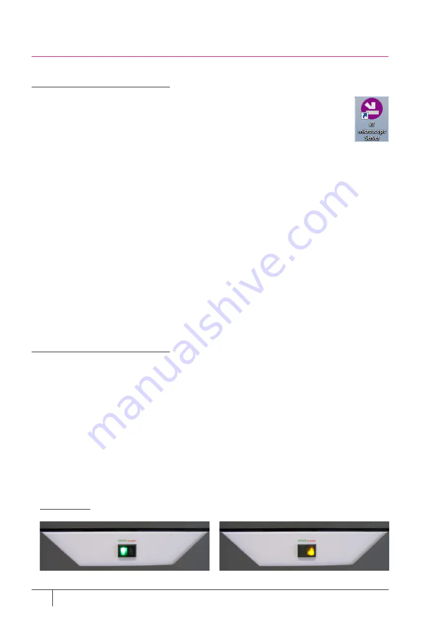
xT microscope Server:
starts and stops basic microscope functions
•
Microscope Control
(
UI
– User Interface): controls all system functions including imaging, image
and movie gathering / manipulation / output, detection and analysis, scanning, magnification,
stage navigation, chamber and column pressure, etc.
•
User Management
: ensures users admission to both the operating system, Windows 7, and the
Microscope Control software
For information on all the features of these applications see Chapter 3.
Password policy
After the software installation there are two initial users / passwords common for the OS Windows and the
Microscope Control software (UI):
•
User: supervisor / Password: supervisor
•
User: user / Password: user
The first time logging into the Windows 7 operating system, a user is automatically forced to change his or her
password. After that the UI accepts it and enables logging in from that point on.
Each password (either for any new user or after the 90 day period expiration) has to meet the following conditions:
•
at least 7 characters long
•
the stem must be significantly different from a previous password and shouldn't contain a complete dictionary
word or user name
•
must contain at least one character from each of these character groups:
– Uppercase letter
– Lowercase letter
– Number
– Symbol (/, *, –,+ etc.)
Hardware
The system is computer-controlled. As such, it has a
Microscope Computer
that must be turned on (use the power
button on the PC) to operate the microscope by means of the software. The
support computer
(option) can hold some
other software utilities. The
switch box
switches the keyboard and the mouse to either of the two computers. The
control software facilities and data are shown graphically on the
LCD monitor
and are superimposed around and on
the image. The other LCD monitor is used either as an extended desktop of the Microscope computer or as the
Support computer monitor. To control software utilities, one can use a
keyboard
, a
mouse
, the
joystick
(option) or the
Manual User Interface
(option).
Power button
The console / system power is activated by pressing the power button located on the microscope console front
panel. This switches the sub-systems on and allows the interface and communication with the Microscope
computer, from which most of the functions are activated via the software control.
The power button indicates several system states:
•
green lit
– the Full Operation state
•
amber lit
– the Standby system state
•
not lit
– the Complete shutdown system state
FIGURE 2-2:
Control panel Power button


