


3
Configuration
ChromQuest Data System Instrument Configuration
32
Accela PDA Detector Hardware Manual
Thermo Scientific
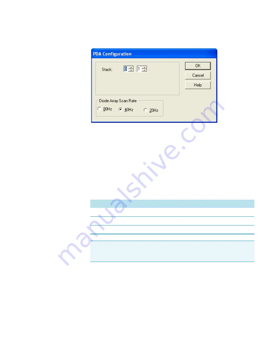
Figure 26.
Accela PDA Configuration dialog box (ChromQuest data system)
g. In the Stack boxes, type or select the stack address.
Unless you are controlling more than one Accela PDA Detector from the same data
system computer, leave the value set to the default of
01
.
The stack address must match the unit ID setting for the two rotary switches
(see
) on the back panel of the PDA detector.
h. In the Diode Array Scan Rate area, select the appropriate scan rate for your
application.
The appropriate diode array scan rate depends on the baseline width (W
b
) of your
application’s chromatographic peaks:
10. Click
OK
to accept the settings and close the Accela PDA Configuration dialog box.
11. Click
OK
to close the Detector Configuration dialog box.
12. If you have not already done so, configure the remaining modules of your Accela LC
stack.
13. Click
OK
to close the Accela dialog box.
14. Click
OK
to close the Instrument Configuration dialog box and return to the
Main Menu window.
Baseline peak width (seconds)
Diode array scan rate (Hz)
W
b
0.5
80
0.5 < W
b
< 1
40
1
W
b
< 2
20
IMPORTANT
When you change the diode array scan rate, you must adjust the
light throughput to the diode array (see
“Adjusting the Light Throughput with
).
≥ ≥
≥ ≥