30
8. Electronic Functions
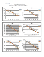
NOTE: The “x” variable for all graphs shown in this section is time.
8.1 Abbreviation
T1: Indoor room temperature
T2: Evaporator coil temperature
T3: Condenser coil temperature
T4: Outdoor ambient temperature
T5: Compressor discharge temperature
8.2 Display Function
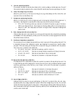
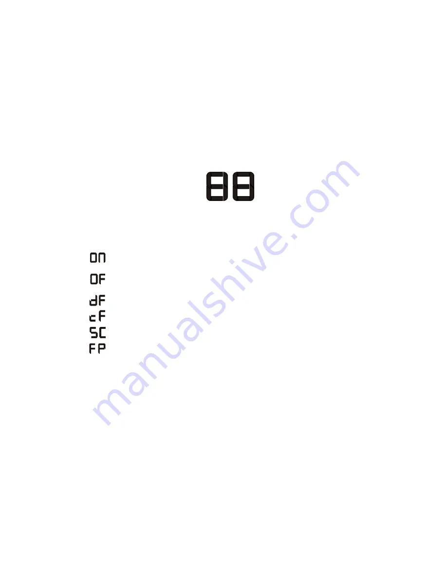
Operating Symbols Displayed in Panel
It displays the temperature settings when the air conditioner is operating.
It displays the room temperature in FAN mode.
Other function display:
:
This code illuminates for 3 seconds when the Timer ON, Swing, Turbo or Silence
function is activated.
:
This code illuminates for 3 seconds when the Swing, Turbo or Silence function is
cancelled or Timer OFF is activated.
:
This code illuminates when unit is defrosting.
:
This code illuminates when anti-cold air function is turned on.
:
This code illuminates when unit is in self-cleaning process.
:
This code illuminates when freeze protection is turned on.
8.3 Protection Features
1.
Three minutes delay at restart for compressor.
1 minute delay for the 1
st
time starting up and 3 minutes delay for other startup times.
2.
Compressor overload protection
If the compressor overload protection is triggered, the unit will stop and then later restart.
3.
Temperature protection of compressor discharge
T5
Compressor discharge temperature.
•
T5 > 239°F
Compressor stops running after 5 seconds.
4.
Fan speed is out of control
When indoor fan speed operates too low (300 rpm) for a certain period of time, the unit will
stop and the
E3
error code will display on the panel.
Содержание 12H47YIMI
Страница 10: ...10 1080 mm 226 mm 335 mm 30H48ZIMI 49 57 1259 mm 11 1 282 mm 14 25 362 mm 36H46ZIMI...
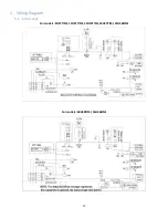
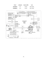
Страница 19: ...19 Model Voltage V Capacity BTU Type 12H47ZOMI 230 12 000 HEAT PUMP...
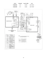
Страница 20: ...20 Model Voltage V Capacity BTU Type 18H47ZOMI 230 18 000 HEAT PUMP 24H46ZOMI 230 24 000 HEAT PUMP...
Страница 21: ...21 Model Voltage V Capacity BTU Type 30H48ZIMI 230 30 000 HEAT PUMP 36H46ZIMI 230 36 000 HEAT PUMP...
Страница 55: ...55 Note The pictures below are only for reference they may be not same as the ones on your unit P U P V...
Страница 56: ...56 P W N U...
Страница 57: ...57 N V N W...
Страница 82: ...82 7 Then lift the PCB assembly off the unit NOTE All wires are still connected...

