Form: 2435-3
Arctic Installation and Operation Manual
Revision: 10
P/N 105641-01
Date: 12-1-2018
Thermal Solutions, 1175 Manheim Pike, Lancaster, PA 17601
Web:
Phone:
717-239-7642
Fax:
877-501-5212
Email:
9
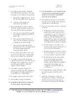
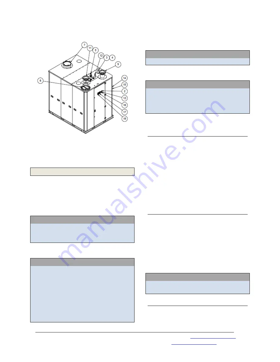
Figure 3: ARC3500-6000 External Boiler
Connections and Components
2
Pre-Installation
The customer should examine the equipment
for any damage. It is the responsibility of the
installer to ensure all parts supplied with the
equipment are fitted in a correct and safe
manner.
WARNING
This boiler requires regular maintenance
and service to operate safely. Follow the
instructions contained in this manual.
WARNING
Improper
installation,
adjustment,
alteration, service, or maintenance can
cause property damage, personal injury or
loss of life. Read and understand the
entire
manual
before
attempting
installation, start-up operation, or service.
Only an experienced, skilled installer or
service agency must perform installation
and service.
WARNING
This boiler must be properly vented.
WARNING
This boiler needs fresh air for safe
operation and must be installed so there
are provisions for adequate combustion
and ventilation air.
2.1
Installation Conformance
Installation must conform to the requirements
of the authority having jurisdiction. In the
absence of such requirements, installation
must conform to the National Fuel Gas Code,
NFPA 54/ANSI Z223.1, and/ or CAN/CGA
B149 Installation Codes. Where required by
the authority having jurisdiction, the
installation must conform to the Standard for
Controls and Safety Devices for Automatically
Fired Boilers, ANSI/ ASME CSD-1.
2.2
Boiler Foundation
Before uncrating, the boiler location should
be prepared. The boiler should set upon a
good level concrete floor. If the boiler is not
level or the floor is not in good condition, a
concrete foundation should be built, the
dimensions being larger than the outside
dimensions of the boiler base. A 4” high
housekeeping pad is suggested.
WARNING
Do not install boiler on combustible
flooring.
2.3
Clearances and Serviceability
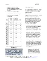
See Figure 4 and Table 2 for minimum
clearances to walls, ceilings, or obstructions.
These clearances are intended as a general


