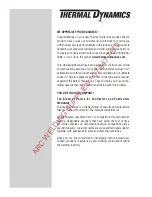
380-
400
Art # A-09206
PLASMA CUTTING SYSTEM
20mm
CUTMASTER
™
Rev. AC Date:
February 25, 2010
Manual #
0-5078
Operating Manual
ARC WELDING SUPPLIES - 07 847 7870
Страница 1: ...380 400 Art A 09206 PLASMA CUTTING SYSTEM 20mm CUTMASTER Rev AC Date February 25 2010 Manual 0 5078 Operating Manual A R C W E L D I N G S U P P L I E S 0 7 8 4 7 7 8 7 0...
Страница 2: ...d the entire manual especially the Safety Precautions They will help you to avoid po tential hazards that may exist when working with this product YOU ARE IN GOOD COMPANY The Brand of Choice for Contr...
Страница 3: ...s work in whole or in part without written permission of the publisher is prohibited The publisher does not assume and hereby disclaims any liability to any party for any loss or damage caused by any...
Страница 4: ...This Page Intentionally Blank A R C W E L D I N G S U P P L I E S 0 7 8 4 7 7 8 7 0...
Страница 5: ...ns And Accessories 2T 2 2T 05 Introduction to Plasma 2T 2 SECTION 3 SYSTEM INSTALLATION 3 1 3 01 Unpacking 3 1 3 02 Lifting Options 3 1 3 03 Primary Input Power Connections 3 1 3 04 Gas Connections 3...
Страница 6: ...placement Power Supply Parts 6 2 6 05 Options and Accessories 6 2 6 06 Replacement Parts for Hand Torch 6 3 6 07 Replacement Parts for Machine Torches with Unshielded Leads 6 4 6 08 Replacement Shield...
Страница 7: ...mony Chromium Mercury Arsenic Cobalt Nickel Barium Copper Selenium Beryllium Lead Silver Cadmium Manganese Vanadium Always read the Material Safety Data Sheets MSDS that should be supplied with the ma...
Страница 8: ...r birth defects and other reproductive harm Wash hands after handling California Health Safety Code 25249 5 et seq 1 03 Publications Refer to the following standards or their latest revisions for more...
Страница 9: ...t des dangers de sant Eloignez toute fum e et gaz de votre zone de respiration Gardez votre t te hors de la plume de fum e provenant du chalumeau Utilisez un appareil respiratoire alimentation en air...
Страница 10: ...nies de parois lat rales ou des lunettes de protection ou une autre sorte de protection oculaire Portez des gants de soudeur et un v tement protecteur appropri pour prot ger votre peau contre les tinc...
Страница 11: ...ciety 550 N W LeJeune Rd Miami FL 33126 8 Norme 51 de l Association Am ricaine pour la Protection contre les Incendies NFPA LES SYSTEMES GAZ AVEC ALIMENTATION EN OXYGENE POUR LE SOUDAGE LA COUPE ET LE...
Страница 12: ...testing for all printed circuit boards used CENELEC EN50199 EMC Product Standard for Arc Welding Equipment ISO IEC 60974 1 BS 638 PT10 EN 60 974 1 EN50192 EN50078 applicable to plasma cutting equipme...
Страница 13: ...nty does not apply to 1 Consumable Parts such as tips electrodes shield cups o rings starter cartridges gas distributors fuses filters 2 Equipment that has been modified by an unauthorized party impro...
Страница 14: ...CUTMASTER 20mm GENERAL INFORMATION 1 8 Manual 0 5078 This Page Intentionally Blank A R C W E L D I N G S U P P L I E S 0 7 8 4 7 7 8 7 0...
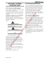
Страница 15: ...below and clicking on Thermal Dynamics and then on the Literature link http www thermal dynamics com 2 02 Equipment Identification The unit s identification number specification or part number model...
Страница 16: ...CE IEC CE IEC CE Current 60A 60A 50A 50A 30A 30A DC Voltage 104 104 100 100 92 92 NOTE The duty cycle will be reduced if the primary input power AC is low or the output voltage DC is higher than show...
Страница 17: ...rd AWG 3 Phase 380 50 60 11 16 11 20 14 400 50 60 11 16 11 20 14 Line Voltages with Suggested Circuit Protection and Wire Sizes Based on National Electric Code and Canadian Electric Code NOTES Refer t...
Страница 18: ...y Features Handle and Leads Wrap Torch Leads Receptacle Control Panel Art A 07942 Work Cable and Clamp Art A 08544 Input Power Cord Port for Optional Automation Interface Cable Gas Inlet Port Filter A...
Страница 19: ...used as both the plasma and second ary gas The air flow is divided inside the torch head Single gas operation provides a smaller sized torch and inexpensive operation NOTE Refer to Section 2T 05 Intr...
Страница 20: ...ch has been heated to an ex tremely high temperature and ionized so that it becomes electrically conductive The plasma arc cutting and gouging processes use this plasma to transfer an electrical arc t...
Страница 21: ...Main Cutting Arc DC power is also used for the main cutting arc The negative output is connected to the torch electrode through the torch lead The positive output is con nected to the workpiece via th...
Страница 22: ...CUTMASTER 20mm INTRODUCTION 2T 4 Manual 0 5078 This Page Intentionally Blank A R C W E L D I N G S U P P L I E S 0 7 8 4 7 7 8 7 0...
Страница 23: ...r power source for correct voltage before plugging in or connecting the unit The primary power source fuse and any extension cords used must conform to local electrical code and the rec ommended circu...
Страница 24: ...ect the opposite end of individual wires to a customer supplied plug or main disconnect 10 Connect the input power cable or close the main disconnect switch to supply power 3 04 Gas Connections Connec...
Страница 25: ...r Filter Kit This optional two stage air line filter is also for use on compressed air shop systems Filter removes moisture and contaminants to at least 5 microns Connect the air supply as follows 1 A...
Страница 26: ...3 The cylinder must be equipped with an adjustable high pressure regulator capable of outlet pressures up to 100 psi 6 9 bar maximum and flows of at least 300 scfh 141 5 lpm 4 Connect supply hose to t...
Страница 27: ...e connection 1 2 Art A 07885 Connecting the Torch to the Power Supply 3 The system is ready for operation Check Air Quality To test the quality of air 1 Put the ON OFF switch in the ON up position 2 P...
Страница 28: ...Pinch Block Assembly Mechanical Torch Set Up 3 The proper torch parts shield cup tip start cartridge and electrode must be installed for the type of operation Refer to Section 4T 07 Torch Parts Selec...
Страница 29: ...s OFF 4 Air Gas Pressure Control The Pressure Control is used in the SET mode to adjust the air gas pressure Pull the knob out to adjust and push in to lock 5 AC Indicator Steady light indicates power...
Страница 30: ...y on Connect Work Cable Clamp the work cable to the workpiece or cutting table The area must be free from oil paint and rust Connect only to the main part of the workpiece do not connect to the part t...
Страница 31: ...ts instantly and the cutting arc restarts instantly when the pilot arc contacts the workpiece Use the Rapid Auto Restart position when cutting expanded metal or gratings or in gouging or trimming oper...
Страница 32: ...CUTMASTER 20mm OPERATION 4 4 Manual 0 5078 This Page Intentionally Blank A R C W E L D I N G S U P P L I E S 0 7 8 4 7 7 8 7 0...
Страница 33: ...lds the tip and starter cartridge in place Position the torch with the shield cup facing upward to keep these parts from falling out when the cup is removed 1 Unscrew and remove the shield cup assem b...
Страница 34: ...ding Rounding on the top edge of a cut due to wearing from the initial contact of the plasma arc on the workpiece Bottom Dross Buildup Molten material which is not blown out of the cut area and resoli...
Страница 35: ...ross When dross is present on carbon steel it is com monly referred to as either high speed slow speed or top dross Dross present on top of the plate is normally caused by too great a torch to plate d...
Страница 36: ...teristic of the power supply and not a function of the torch 3 4 Art A 03383 Trigger 2 1 Trigger Release 6 Cut as usual Simply release the trigger assembly to stop cutting 7 Follow normal recommended...
Страница 37: ...ng technique that feels most comfort able and allows good control and move ment 4 Keep the torch in contact with the work piece during the cutting cycle 5 Hold the torch away from your body 6 Slide th...
Страница 38: ...rch handle while simultaneously squeezing the trigger The pilot arc will start A 02986 Trigger Trigger Release 6 Bring the torch within transfer distance to the work The main arc will transfer to the...
Страница 39: ...hand or machine torch and the amount of material to be removed Lead Angle The angle between the torch and workpiece depends on the output current setting and torch travel speed The recommended lead a...
Страница 40: ...rc column produces the cut If the travel speed is too slow a rough cut will be produced as the arc moves from side to side in search of metal for transfer Travel speed also affects the bevel angle of...
Страница 41: ...Shield Cap Deflector 9 8243 Shield Cup Body 9 8237 Shield Cup 9 8218 Tip Tips Tips Tips DRAG TIP CUTTING 40 120A GOUGING CUTTING CUTTING CUTTING Art A 08065_AE DRAG SHIELD CUTTING Shield Cap Deflecto...
Страница 42: ...si bar Plasma Total Delay Sec Inches mm 0 036 0 9 9 8208 103 40 355 9 02 0 125 3 2 70 4 8 55 170 0 00 0 2 5 1 0 05 1 3 9 8208 98 40 310 7 87 0 125 3 2 70 4 8 55 170 0 00 0 2 5 1 0 06 1 5 9 8208 98 40...
Страница 43: ...0 750 19 1 9 8210 142 60 12 0 31 0 25 6 4 75 5 2 90 245 NR NR NR Type Torch SL60 With Exposed Tip Type Material Mild Steel Type Plasma Gas Air Type Secondary Gas Single Gas Torch Thickness Tip Output...
Страница 44: ...9 8210 116 60 250 6 35 0 25 6 4 75 5 2 90 245 0 10 0 25 6 4 0 188 3 4 9 8210 116 60 170 4 32 0 25 6 4 75 5 2 90 245 0 20 0 25 6 4 0 250 6 4 9 8210 132 60 85 2 16 0 25 6 4 75 5 2 90 245 0 30 0 25 6 4 0...
Страница 45: ...si bar Plasma Total Delay Sec Inches mm 0 036 0 9 9 8208 109 40 180 4 57 0 125 3 2 70 4 8 55 170 0 00 0 2 5 1 0 05 1 3 9 8208 105 40 165 4 19 0 125 3 2 70 4 8 55 170 0 00 0 2 5 1 0 06 1 5 9 8208 115 4...
Страница 46: ...165 4 19 0 13 3 2 75 5 2 90 245 0 00 0 20 5 1 0 075 1 9 9 8210 116 60 155 3 94 0 13 3 2 75 5 2 90 245 0 10 0 20 5 1 0 120 3 0 9 8210 115 60 125 3 18 0 13 3 2 75 5 2 90 245 0 10 0 20 5 1 0 135 3 4 9 82...
Страница 47: ...N NOTES Gas pressure shown is for torches with leads up to 25 7 6 m long For 50 15 2 m leads refer to section 4 02 Operating Pressure Total flow rate includes plasma and secondary gas flow A R C W E L...
Страница 48: ...6933461 Other Pat s Pending 9 8211 Tip US Pat No s 6774336 7145099 6933461 Other Pat s Pending 9 8212 Tip US Pat No s 6774336 7145099 6933461 Other Pat s Pending 9 8253 Tip US Pat No s 6774336 714509...
Страница 49: ...D496951 Other Pat s Pending The following parts are also licensed under U S Patent No 5 120 930 and 5 132 512 Catalog Description 9 8235 Shield Cap 9 8236 Shield Cap 9 8237 Shield Cup 9 8238 Shield C...
Страница 50: ...CUTMASTER 20mm OPERATION 4T 18 Manual 0 5078 This Page Intentionally Blank A R C W E L D I N G S U P P L I E S 0 7 8 4 7 7 8 7 0...
Страница 51: ...ode Weekly Visually inspect the torch body tip electrode start cartridge and shield cup Visually inspect the cables and leads Replace as needed 3 Months Clean exterior of power supply 6 Months Replace...
Страница 52: ...ing Blowing air into the unit can cause metal particles to interfere with sensitive electrical components and cause damage to the unit 5 03 Common Faults Problem Symptom Common Cause Insufficient Pene...
Страница 53: ...d 75 psi indicators are on indicating the version would be 2 3 A PSI BAR MAX MAX MIN MIN 1 2 3 4 Art A 07988 MIN MAX 0 1 2 3 4 5 6 7 5 When the Fault indicator is on or blinking it will be accompanied...
Страница 54: ...ponents in unit 1 Refer to clearance information section 2 04 2 Allow unit to cool 3 Return to authorized service center for repair or replacement GAS LED off FAULT and MIN pressure indicators flashin...
Страница 55: ...rts 4 Shorted Torch 5 Temporary Short indicated by 5 blinks per second 6 Power Supply Failure Standard rate of blinking 1 Remove shield cup from torch check upper O Ring position correct if necessary...
Страница 56: ...r onto the power supply so that slots in the bottom edges of the cover engage the lower screws 3 Tighten lower screws 4 Reinstall and tighten the upper screws C Filter Element Assembly Replacement The...
Страница 57: ...ally when the Filter Element becomes completely saturated The Filter Element can be removed from its housing dried and reused Allow 24 hours for Element to dry Refer to Section 6 Parts List for replac...
Страница 58: ...ts on the top of the Filter As sembly enough to allow the Filter Elements to move freely 4 Note the location and orientation of the old Filter Elements 5 Slide out the old Filter Elements First Second...
Страница 59: ...ith compressed air CAUTION Dry the torch thoroughly before reinstalling O Ring Lubrication An o ring on the Torch Head andATC Male Connec tor requires lubrication on a scheduled basis This will allow...
Страница 60: ...the shield cup body and drag shield cap Do not lubricate the O ring Drag Shield Cap Shield Cup Body O Ring No 8 3488 Art A 03878 4 Remove the tip Check for excessive wear indi cated by an elongated or...
Страница 61: ...iza tion will not be accepted 6 02 Ordering Information Order replacement parts by catalog number and complete description of the part or assembly as listed in the parts list for each type item Also i...
Страница 62: ...1 Two Stage Air Filter Assembly 9 7527 1 First Stage Cartridge 9 1021 1 Second Stage Cartridge 9 1022 1 Extended Work Cable 50 ft 15 2 m with Clamp 9 8529 1 Multi Purpose Cart 7 8888 1 Automation Int...
Страница 63: ...9 8219 5 1 Large O Ring 8 3487 6 1 Small O Ring 8 3486 7 Leads Assemblies with ATC connectors includes switch assemblies 1 SL60 20 foot Leads Assembly with ATC connector 4 7834 1 SL60 50 foot Leads As...
Страница 64: ...d Mechanized Leads Assemblies with ATC connectors 1 5 foot 1 5 m Leads Assembly with ATC connector 4 7842 1 10 foot 3 05 m Leads Assembly with ATC connector 4 7843 1 25 foot 7 6 m Leads Assembly with...
Страница 65: ...CUTMASTER 20mm Manual 0 5078 6 5 PARTS LIST A 07994 6 1 4 2 3 5 7 8 9 10 12 11 10 A R C W E L D I N G S U P P L I E S 0 7 8 4 7 7 8 7 0...
Страница 66: ...nectors 1 5 foot 1 5 m Leads Assembly with ATC Connector 4 7846 1 10 foot 3 05 m Leads Assembly with ATC Connector 4 7847 1 25 foot 7 6 m Leads Assembly with ATC Connector 4 7848 1 50 foot 15 2 m Lead...
Страница 67: ...d Cap Deflector 9 8243 Shield Cup Body 9 8237 Shield Cup 9 8218 Tip Tips Tips Tips DRAG TIP CUTTING 40 120A GOUGING CUTTING CUTTING CUTTING Art A 08065_AE DRAG SHIELD CUTTING Shield Cap Deflector 9 82...
Страница 68: ...Cup Body 9 8237 Shield Cup 9 8218 Shield Cap Deflector 9 8243 Shield Cup Body 9 8237 Shield Cup 9 8218 Shield Cap Machine 50 60A 9 8238 Drag Shield Cup 9 8235 Drag Shield Cup 70 100A 9 8236 Drag Shiel...
Страница 69: ...RUN Rapid Auto Restart SET LATCH switch to RUN for most applications or to Rapid Auto Restart for gouging trimming or expanded metal applications or to LATCH is used for specific applications torch s...
Страница 70: ...s Second row Rated cutting current values Third row Conventional load voltage values 4 Sections of the Data Tag may be applied to separate areas of the power supply I Art A 03288 Date of Mfr Output Ra...
Страница 71: ...e Plasma 8 Ground ATC Male Connector Front View A 03701 B Mechanized Machine Torch Pin Out Diagram ATC Female Receptacle Front View ATC Male Connector Front View Negative Plasma 3 White Pendant Connec...
Страница 72: ...Torch Switch Green White To Power Supply Circuitry B Mechanized Torch Connection Diagram Torch Unshielded Mechanized SL100 Machine Torch Leads Leads with ATC Connector and Remote Pendant Connector Pow...
Страница 73: ...CUTMASTER 20mm Manual 0 5078 A 5 APPENDIX This Page Intentionally Blank A R C W E L D I N G S U P P L I E S 0 7 8 4 7 7 8 7 0...
Страница 74: ...CABLE SIGNALS LATCH SET RUN RAR 40 CIRCUIT RIBBON CABLE MAX 90 85 80 75 70 65 MIN J2 7 D1 L1 L2 L3 GND D C AIR INLET FILTER REGULATOR SOLENOID VALVE TP1 TP2 TP3 TP4 TP5 TP6 TP7 ATC MAIN PCB ASSY LOGI...
Страница 75: ...tten Consent NOTE UNLESS OTHERWISE SPECIFIED 1 RESISTOR VALUES ARE EXPRESSED IN OHMS 1 4W 5 2 CAPACITOR VALUES ARE EXPRESSED IN MICROFARADS uF Chk App TITLE Last Modified Size SCHEMATIC 42X1329 Wednes...
Страница 76: ...ion History Cover Date Rev Change s Sept 18 2008 AA Manual released May 27 2009 AB Updated 400V 600V schematic in appendix per ECOB1399 Feb 25 2010 AC Updated CNC cable part numbers in section 6 per E...
Страница 77: ...e 86 21 69171135 Fax 86 21 69171139 Thermadyne Asia Sdn Bhd Lot 151 Jalan Industri 3 5A Rawang Integrated Industrial Park Jln Batu Arang 48000 Rawang Selangor Darul Ehsan West Malaysia Telephone 603 6...
Страница 78: ...orporate Headquarters 16052 Swingley Ridge Road Suite 300 St Louis MO 63017 Telephone 636 728 3000 Email TDCSales Thermadyne com www thermadyne com A R C W E L D I N G S U P P L I E S 0 7 8 4 7 7 8 7...