EUROPA SERIES USER MANUAL
18
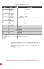
CONTINUED FROM PREVIOUS TABLE
Note:
1.
Typical value of power supply is 4 V DC; here refers to the voltage value of the thermal camera
connector, power setup time (10% ~ 90%) < 4 mS, peak current > 1.0 A, ripple and noise < 40
mVp-p.
2�
All the TX and RX of serial communication interfaces refer to the thermal camera’s sending
and receiving.
3.
GND and VGND are shorted internally.
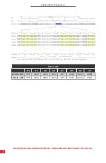
PLEASE READ AND UNDERSTAND THE TABLES BEFORE SWITCHING THE UNIT ON.
NO.
Name
Type
Description
47
L
Output
LVDS_H
(VCCIO=2.5V)
Clock Signal
49
LVDS_CLK-
51
LVDS_
DATA0+
Data
53
LVDS_DATA0-
57
LVD
Data
58
LVDS_DATA1-
61
LVDS_
DATA2+
Data
63
LVDS_DATA2-
65
LVDS_
DATA3+
Data
67
LVDS_DATA3-
58
IO0
Input/
Output
Reserved
60
IO1
Reserved
62
IO2
Reserved
64
IO3
Reserved
66
IO4
Reserved
68
IO5
Reserved
5, 6, 7, 8, 13,
14, 17, 18, 43,
44, 55, 56,
69, 70
GND
Power Ground of power supply
3


