background image


7-5


User Manual PN 84469 Rev L 

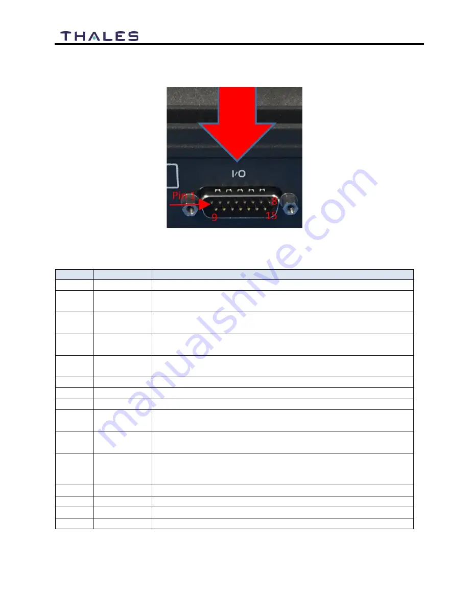
Connector Location 

The DB-15 connector with Pin out shown in Figure 7-2. 


Figure 7-2 GPIO Connector Pin Detail 


Table 7-2 GPIO Connector Pin Definition 

Pin No 

Name 

Description 

GND1 

Ground  

Au 

Radio Gateway functionality, differential (+) Hi-Z Audio Input from 
external Radio 

Aud  Radio Gateway functionality, Differential (+) Low-Z Audio Output 

to external radio (mic input) 

RadioCOR 

Radio Gateway functionality, Radio initiated voice into terminal 
(optional) 

EMER_IN 

Emergency remote functionality, Ground pin to activate internal 
Emergency 

GPI01 

Software configurable GPIO pin #1  

RS232_TD 

RS232 Output (future) 

GND2 

Ground 

Audio_In - 

Radio Gateway functionality, differential (-) Hi-Z Audio Input from 
external Radio 

10 

Audio_Out - 

Radio Gateway functionality, Differential (-) Low-Z Audio Output 
to external radio (mic input) 

11 

RadioPTT 

Radio Gateway functionality, Output PTT from terminal to external 
radio, short to ground for PTT enabled, Open drain requires external 
10k pullup resistor 

12 

GND3 

Ground 

13 

GPI02 

Software configurable GPIO pin #2  

14 

RS232_RD 

RS232 Input (future) 

15 

12V 

+12V output, 100mA 


Содержание VesseLINK Certus 200

Страница 1: ... DEFENSE SECURITY INC ALL RIGHTS RESERVED This document contains technology controlled for export by the U S Department of Commerce in accordance with Export Administration Regulations Diversion contrary to U S law prohibited Thales VesseLINK User Manual for Certus 350 and Certus 200 Systems ...

Страница 2: ...gging Satellite connection monitoring SPeters Rev L Sep 2022 ECN 54856 Handset updates for PTT App support GPIO feature addition SPeters WARNING INFORMATION SUBJECT TO EXPORT CONTROL RESTRICTIONS This document contains technology controlled for export by the U S Department of Commerce in accordance with Export Administration Regulations EAR Diversion contrary to U S law prohibited Include this not...

Страница 3: ...f Thales or any third party software providers except for the normal nonexclusive royalty free license to use that arises by operation of law in the sale of a product Content Copyright User is exclusively responsible for the use of this product including proper use of third party copyrighted materials If the User violates these terms the User agrees to defend indemnify and hold Thales harmless wit...

Страница 4: ...LES MANAGEMENT PORTAL 4 2 Menu Components 4 3 Main Dashboard 4 7 Status 4 9 Alerts 4 13 Calls 4 14 Emergency 4 15 Settings 4 16 System 4 55 Diagnostics 4 60 About 4 63 Help 4 64 FIRMWARE UPGRADE 5 1 INSTALLING THE FIRMWARE ON VESSELINK 5 1 MAINTENANCE 6 1 GENERAL 6 1 PREVENTIVE MAINTENANCE 6 1 Inspection and Cleaning 6 1 TROUBLESHOOTING 6 1 SYSTEM RESETS 6 5 ALERTS 6 8 TECHNICAL SPECIFICATIONS 7 1...

Страница 5: ... INSTALLING SIM CARD AND ENGAGING THE LOCK 3 4 FIGURE 3 5 SECURE THE SIM CARD COVER 3 4 FIGURE 3 6 SYSTEM SATELLITE AND WI FI STATUS LEDS 3 5 FIGURE 3 7 VESSELINK USER INTERFACE LOGIN 3 7 FIGURE 4 1 QUICK LINK ICONS 4 4 FIGURE 4 2 QUICK LINK SYSTEM STATUS 4 5 FIGURE 4 3 QUICK LINK SATELLITE STATUS 4 5 FIGURE 4 4 QUICK LINK WI FI STATUS 4 6 FIGURE 4 5 QUICK LINK LAN 1AND LAN 2 STATUS LAN 3 SIMILAR ...

Страница 6: ...EN 4 51 FIGURE 4 41 SETTINGS GPIO 4 53 FIGURE 4 42 SETTINGS LOCATION SERVICES SCREEN 4 54 FIGURE 4 43 SYSTEM BACKUP SCREEN 4 55 FIGURE 4 44 SYSTEM DATA USAGE SCREEN 4 57 FIGURE 4 45 RESET DATA USAGE SCREEN 4 57 FIGURE 4 46 SYSTEM RESET 4 58 FIGURE 4 47 SYSTEM FIRMWARE SCREEN 4 59 FIGURE 4 48 FIRMWARE SCREEN SHOW DETAILS 4 60 FIGURE 4 49 DIAGNOSTICS SELF TEST SCREEN 4 61 FIGURE 4 50 PERFORM SELF TE...

Страница 7: ... 10 SETTINGS SURELINK HANDSET 4 39 TABLE 4 11 SETTINGS RADIO GATEWAY 4 42 TABLE 4 12 SETTINGS DATA 4 45 TABLE 4 13 SETTINGS SECONDARY DATA FLOWS 4 48 TABLE 4 14 SETTINGS GLOBAL NAVIGATION SATELLITE SYSTEM 4 50 TABLE 4 15 SETTINGS GPIO 4 53 TABLE 4 16 SETTINGS LOCATION SERVICES 4 55 TABLE 6 1 TROUBLESHOOTING 6 1 TABLE 6 2 ALERTS ERROR MESSAGES 6 8 TABLE 7 1 TECHNICAL SPECIFICATIONS 7 1 TABLE 7 2 GP...

Страница 8: ... place at all times on the Below Deck Unit BDU and Above Deck Unit ADU to maintain the warranty terms Make sure the system is correctly grounded and power is off when installing configuring and connecting components WARNING DO NOT OPERATE IN AN EXPLOSIVE ATMOSPHERE This equipment is not designed to be operated in explosive environments or in the presence of combustible fumes Operating this or any ...

Страница 9: ...istance from the antenna The antenna should be mounted in an area that prevents the possibility of close exposure to the antenna s radiation For the Certus 350 antenna please remain at least 1 5m 4 9 feet from the antenna while in operation For the Certus 200 antenna please remain at least 0 5m 20 inches from the antenna while in operation Certus 350 Certus 200 NOTE Este Equipamento não tem direit...

Страница 10: ...generates uses and can radiate radio frequency energy and if not installed and used in accordance with the instructions may cause harmful interference to radio communications However there is no guarantee that interference will not occur in a particular installation If this equipment does cause harmful interference to radio or television reception which can be determined by turning the equipment o...

Страница 11: ...dustry Canada to operate with the antenna listed in Table 7 1 with the maximum permissible gain and required antenna impedance for each antenna type indicated Antenna types not included in this list having a gain greater than the maximum gain indicated for that type are strictly prohibited for use with this device Le présent émetteur radio 473C VF350BM ou 473C VF200BM a été approuvé par Industrie ...

Страница 12: ...xii Uer Manual PN 84469 Rev L ...

Страница 13: ...xiii Uer Manual PN 84469 Rev L ...

Страница 14: ...na Equipment Applicability The VesseLINK and MissionLINK provide voice and high speed data communication over 100 of the globe through the Iridium Certus broadband Satellite system Declaration The health requirement is met by conforming to EU standard EN 623 11 The safety requirement is met by conforming to EN 60950 1 2006 w A2 2013 for Certus 350 and to EN 62368 1 2014 for Certus 200 The electrom...

Страница 15: ...xv Uer Manual PN 84469 Rev L ...

Страница 16: ...xvi Uer Manual PN 84469 Rev L ...

Страница 17: ...xvii Uer Manual PN 84469 Rev L ...

Страница 18: ...xviii Uer Manual PN 84469 Rev L ...

Страница 19: ...on described in the figures ABOUT THIS MANUAL This user manual is intended for anyone who intends to operate and configure the Thales VesseLINK system It covers both the Certus 350 and the Certus 200 system operation and features It however cannot cover all topics and advanced features For questions or topics that are not covered in this manual please contact your airtime provider or Thales at www...

Страница 20: ...oice or data call is sent to the closest satellite overhead that has a high signal strength The traffic is then routed through the satellite network to a Ground Station or Gateway At the gateway traffic is converted back to internet protocol IP and voice depending on call type and delivered to the IP cloud or the public switched telephone network PSTN Figure 1 2 Typical Iridium network flow of a v...

Страница 21: ...of the sky is necessary as satellites can be as low as eight degrees above the horizon The service capabilities of the system are outlines below Certus Multi Services Platform Satellite data sessions up to 352kbps uplink and 704kbps downlink for Certus 350 systems and 176kbps uplink and 176kbps downlink for Certus 200 systems Up to 3 high quality Iridium voice lines Figure 2 1 Calling Overview for...

Страница 22: ...ar Wi Fi etc Secondary Data Flows SDF maps specialized data services to physical ports GNSS capability allows configuration of multiple satellite constellations including GPS GLONASS Galileo and Beidou for precise autonomous geo spatial positioning Low profile IP66 IP67 Certus 350 Certus200 rated antenna with single RF cable to the Below Deck Unit BDU Radio Gateway feature enables Land Mobile radi...

Страница 23: ...tems such as a POTS phone VoIP phones and a computer is shown in Figure 2 3 A cellular modem or other network modem can be connected to the WAN port for data least cost routing operations Voice calls are always routed through the Iridium system and not the WAN port Figure 2 3 Thales VesseLINK System with Accessories ...

Страница 24: ...d one RJ14 connector enables the user to tether directly to the BDU if desired The Management Portal is a graphical user interface that can be used to modify system settings and indicate system status The BDU is powered by either an AC DC power supply or a DC power cable with a 10 32V input range and remote start wire accommodating all types of marine vessels applications and power sources Figure ...

Страница 25: ... Acquiring satellite Solid RED Fault minor issue Flashing RED Critical fault major issue Wi Fi OFF Wi Fi OFF Flashing GREEN Wi Fi busy Solid Green System functioning properly Solid RED Fault minor issue Flashing RED Critical fault major issue NOTE The Indicator Colors are Solid Green Operational Flashing Green start up or in progress of configuring or acquiring service Solid Red fault requires use...

Страница 26: ...hernet based devices and one WAN Wide Area Network connector primarily used to connect an external cellular modem or VSAT Figure 2 6 Below Deck Unit BDU Front Panel Detail The BDU back panel left to right has a Wi Fi antenna connector reset button SIM Card slot GPIO I O connector 10 32Volt DC input connector 12Volt DC power input antenna connector and chassis grounding lug Figure 2 7 Below Deck Un...

Страница 27: ... of 10 dB or less in the L band frequency of operation 1616 1626 MHz Thales accessory cables listed below have been selected to meet this criteria DC losses due to cable resistance inner conductor and shield The VesseLINK system is designed to work with a maximum total RF cable ohmic resistance of 1 10 Ohms round trip inner conductor and shield Thales accessory cables listed below meet this criter...

Страница 28: ...2 8 User Manual PN 84469 Rev L THIS PAGE INTENTIONALLY LEFT BLANK ...

Страница 29: ...Splitter the two POTS phones can each have a separate phone line not two phones using the same phone line Note that single molded plastic piece RJ 14 Splitters triplex jacks will not fit into the POTS phone connector It is recommended that a POTS Splitter be used that includes a short phone cord that fits into the BDU POTS connector VoIP or Thales SureLINK IP Phone connection By default the BDU ha...

Страница 30: ... to any extension even those assigned to the POTS lines The SureLINK IP Handset will have a default of 1002 or extension 21 so it will automatically work the same as the first POTS line STEP 2 Know your VesseLINK It may be necessary to know details about your VesseLINK system when calling for help or service IMEI is unique to each unit and can be found on the back plate of the BDU This IMEI can al...

Страница 31: ...the SIM Card protective cover by pulling it away from the BDU exposing the SIM card slot Figure 3 3 Figure 3 3 SIM Card with Cover Opened 2 Install SIM card from Air time provider 1 Figure 3 4 by inserting the card with contacts down 2 until it clicks into place 3 3 Be sure to engage the lock for the SIM Card 4 ...

Страница 32: ... If using the AC DC power supply connect one end to the BDU s 12V DC input and connect the power cord to a 120V or 240V AC outlet The antenna must also be connected per the system installation manual Power the unit by pressing and releasing the power button on the BDU Figure 3 1 NOTE After the button is pressed and released a few seconds pass before the System LED left starts flashing It may take ...

Страница 33: ...p Solid RED Fault minor issue Flashing RED Critical fault major issue Satellite Solid BLUE Connected and passing data over satellite Solid GREEN System functioning properly Flashing GREEN Acquiring satellite Solid RED Fault minor issue Flashing RED Critical fault major issue Wi Fi OFF Wi Fi OFF Flashing GREEN Wi Fi busy Solid Green System functioning properly Solid RED Fault minor issue Flashing R...

Страница 34: ...no changes to setup are necessary but advanced users may want to configure their preferred system settings 5 Once the Management Portal opens click LOGIN button Enter admin for Login ID and Password 6 At this time it is advised that you change the Management Portal admin password To change password Go to SETTINGS GENERAL and change the password for the Admin user A strong password is required that...

Страница 35: ...E If you forget the password press and hold the reset pin on the back of the box while powered on in order to reset the system to factory settings All custom configuration settings will be lost Figure 3 7 VesseLINK User Interface Login ...

Страница 36: ...own number to test call and voice clarity Call the Iridium automated message 9 1 480 752 5105 STEP 7 Access the Internet Once your device has successfully connected to the BDU open the Management Portal http portal thaleslink or https portal thaleslink to verify the satellite connection Verify No active alerts DASHBOARD or ALERTS page on the Management Portal Satellites detected go to STATUS SERVI...

Страница 37: ... with a lowercase letter an uppercase letter a number and a special character NOTE To access the Management Portal from a wireless device using Wi Fi Power on the VesseLINK BDU and let it boot up may take a few minutes On the wireless device find and select ThalesLINK as an available Wi Fi access point Open a browser and type http portal thaleslink or https portal thaleslink do not type com or any...

Страница 38: ...ead of a local user The second remote access level is for remote administrators such as Service Providers This level allows for viewing all data and making configuration changes through the custom Thales Application Programming Interface API The guest access level is not password protected so when the Management Portal is opened the guest user can view the current configuration and status of the s...

Страница 39: ...ministrator to run a self test check system status and view the diagnostics log About Provides system level information for the antenna modem power supply system VoIP Module and Wi Fi Help Provides a link to the VesseLINK User Documentation Users Guide Installation Instructions and Quick Start Guide QSG NOTE Depending on the web browser being used you may see a message that says NOT SECURE If you ...

Страница 40: ...al Strength System Status The System Status icon provides a quick view of the state of the system It mirrors the status of the System LED on the BDU Selecting the System Status icon brings up the additional information in Figure 4 2 o STATUS shows the current condition of the system o UPTIME indicates how long the terminal has been in use o The RESTART button allows an administrator to reboot the ...

Страница 41: ...ting the Satellite Status icon displays the information in Figure 4 3 showing Connection Status Signal Strength and the Current Data Path Selecting ACTIVATE DEACTIVATE enables and disables data sessions Changes will take effect once SAVE CHANGES is selected Selecting VIEW STATUS will open the STATUS SERVICES Window Figure 4 3 Quick Link Satellite Status Wi Fi Status The Wi Fi Status icon provides ...

Страница 42: ...erence source not found is shown displaying the Link Status and allowing for turning the Power over Ethernet PoE ON or OFF for that LAN as well as enabling or disabling the PAN port Only LAN 2 and 3 can be disabled LAN port 1 is always enabled to prevent a situation where the terminal cannot be accessed Changes will only take effect once SAVE CHANGES is selected Figure 4 5 Quick Link LAN 1and Lan ...

Страница 43: ...th rises Main Dashboard When first accessing the Management Portal by typing in http portal thaleslink or https portal thaleslink the Dashboard screen comes up by default The Dashboard also appears by selecting the top menu item highlighted in blue in Figure 4 7 From the Dashboard you can see information relating to Current Alerts Services Figure 4 7 Thales VesseLINK Dashboard Main Screen ...

Страница 44: ...s Data Session Deactivate or Activate Allows the admin to activate or deactivate the Data Session Satellite Connection Disconnected Connected Access Acquisition and Idle Displays the current status of the system when connected to a satellite Signal Strength Indicates the strength of the signal Displays the current satellite signal strength in dBm WAN Connection Disconnected or Connected Displays w...

Страница 45: ... Devices Displays all devices currently connected to the Below Deck Unit BDU both wired and via Wi Fi Wi Fi CLIENTS list shows the MAC Address Hostname and IP Address for the current Wi Fi connected devices ALLOCATED IPs list shows the MAC address hostname and IP Address for all devices that have recently been connected to the BDU Figure 4 8 Status Current Devices Screen ...

Страница 46: ...operator will have access to detailed GPS information as shown in Figure 4 9 Figure 4 9 Status GPS Screen LAN The LAN page displays the connection status of the built in Wi Fi access point and the LAN ports as shown in Figure 4 10 Figure 4 10 Status LAN Screen ...

Страница 47: ... that are connected to the system including the extension that was assigned as shown in Figure 4 11 Figure 4 11 Status PHONES Screen Services The Services page provides the status of Satellite and WAN networks and the current data route as shown in Figure 4 12 Figure 4 12 Status SERVICES Screen ...

Страница 48: ... and its Private IP Address The max data rate shows the Certus service level that the SIM card is provisioned to Voice Lines This section lists the dedicated Iridium voice lines up to three what type they are and what their MSISDN is Secondary Data Flows SDF shows which are provisioned on the SIM and the Subnet they are on Figure 4 13 Status SIM Screen ...

Страница 49: ...Active Alerts NOTE For additional information refer to Chapter 6 Troubleshooting Alerts may be generated from a Power On Self Test POST or during normal operation of the system Figure 4 15 The alerts indicate that something may be wrong with the system or network The alerts will clear if they are no longer affecting the system operation When cleared the SYSTEM STATUS icon will turn GREEN Figure 4 ...

Страница 50: ...call logs for active and past calls Figure 4 16 Call Log Screen Under CALL LOG MANAGEMENT Figure 4 17 the operator can CLEAR the call log by selecting CLEAR LOG and then confirming by selecting YES CLEAR LOG Figure 4 17 CLEAR Call Log NOTE CALL HISTORY displays the last 100 calls that were made ...

Страница 51: ...Figure 4 18 menu item allows for enabling and sending an emergency email message Selecting MANAGE EMERGENCY will open the SETTINGS EMERGENCY screen Figure 4 22 From here set up the Emergency Message by selecting Email from the drop down box Once the required email information has been entered including the message to be sent select APPLY For additional information refer to SETTINGS EMERGENCY Figur...

Страница 52: ...ettings The Settings tab of the portal is the most important section for customizing user configurations and feature settings It is also advised that only experienced personnel change these settings as they may adversely affect functionality if not set correctly These settings are under password control to prevent unauthorized personnel from making changes to the system General From the General pa...

Страница 53: ...d from the default a strong password is required that has at least 8 characters with a lowercase letter an uppercase letter a number and a special character Figure 4 21 Settings General Screen Table 4 3 Settings General Settings Section Parameters Change Password Select User Currently there are 3 choices Admin WAN_Admin and WAN_User Enter NEW Password and confirm the new password Note Minimum of 8...

Страница 54: ...the admin can set up an emergency message The Management Portal configuration is restricted to a distress email only Select EMAIL from the pull down list Figure 4 22 Enter the required information shown in Table 4 4 example data shown in Figure 4 23 along with the message to be sent and select APPLY NOTE Selecting APPLY does not send a distress message It saves the settings and message Sending the...

Страница 55: ...etting Login Required Select either YES or NO YES is the default setting User Enter the user email address Password Enter the user name password Recipient Enter the recipient s email address Message Enter the Emergency message to be sent Satellite The Satellite page shown in Figure 4 24 allows configuration of the data service The configuration includes configuring whitelists and blacklists for do...

Страница 56: ...t select the button BEFORE selecting the button After selecting the button the domain can always be edited or deleted using the buttons BEFORE selecting the button to save If the button is not selected before leaving the Satellite menu item the data will not be saved Figure 4 24 Settings Satellite Screen ...

Страница 57: ...ed if the configured port for that service is changed Port Whitelist Enter the Starting Port and Ending Port number Select the applicable protocol TCP UDP or TCP only or UDP only TCP UDP is the default setting Data Usage System Data Usage Warning Threshold Data limit in kB 1000 bytes 0 means no data and 1 means unlimited data Setting data limits is for information purposes only No data restriction...

Страница 58: ...4 22 User Manual PN 84469 Rev L Figure 4 25 Settings Wi Fi Screen ...

Страница 59: ...network This is done by entering the MAC address of the device example 01 23 45 67 89 ab All others are prevented from accessing it See below note for finding a device s MAC address Assign a Nickname to the MAC Address NOTE Once the initial Wi Fi WPA2 Security Key is entered it can be changed at any time by just overwriting the current Security Key in the SETTINGS Wi Fi WIRELESS GENERAL area NOTE ...

Страница 60: ... the ADMIN to continue Otherwise this is a view only screen The LAN page shown in Figure 4 26 allows PoE to be enabled or disabled on the three LAN ports and DHCP to be enabled and configured or disabled Each LAN port PoE is Class 2 and capable of providing up to 6 5 watts of power to the connected device See ...

Страница 61: ...4 25 User Manual PN 84469 Rev L Table 4 7 for more information on the information that is entered NOTE Please use portal thaleslink as the NTP server ...

Страница 62: ...4 26 User Manual PN 84469 Rev L Figure 4 26 Settings LAN Screen ...

Страница 63: ...way address assigned to the router that connects the terminal to the network LAN MAC Address MAC Address Enter the MAC address same for all LAN switches DHCP Enable DHCP Disabled Enabled Enabled is the default setting IP Address Enter the IP Address Mask Enter the Mask Number Start Enter the starting value for the octet End Enter the ending value for the octet Lease Time Enter the Lease Time being...

Страница 64: ...ton the domain can always be edited or deleted using the buttons BEFORE selecting the button to save If the button is not selected before leaving the WAN menu item the data will not be saved NOTE Caches local to the computer connected to the ThalesLINK terminal will continue to allow data access to blacklisted domains until their DNS cache entry expires To help this take effect sooner clear the lo...

Страница 65: ...4 29 User Manual PN 84469 Rev L Figure 4 27 Settings WAN Screen ...

Страница 66: ...klisting Enabling allows ALL websites EXCEPT those listed very little restriction Whitelisting Enabling blocks ALL websites EXCEPT those listed the most restriction Port Blocking Port Blocking Disabled Enabled Disabled is the default setting Whitelist Service With Port Blocking Enabled this allows for certain essential services Location Services Emergency Services and the Remote API to stay whitel...

Страница 67: ... are saved only after the APPLY button is selected Each of the three Iridium phone lines Inbound can be mapped to ring only one extension The extension is selected from the pull down menu Configuration of analog devices such as the POTS phones and the Radio Gateway are configured on this page Each of these devices can be mapped to an extension Finally in the Phone Configuration area call logs can ...

Страница 68: ...4 32 User Manual PN 84469 Rev L Figure 4 28 Settings Phone Screen ...

Страница 69: ...idium line Inbound Iridium Lines 1 88888 Maps each inbound Iridium line to a single extension previously set up 1001 1003 Default extensions 1001 1002 and 1003 are mapped to Line 1 Line 2 and Line 3 respectively Section Value Device Mapping POTS Assigns extensions to POTS 1 and POTS 2 phones Note 2 POTS phones can be attached with a splitter to the POTS connector Radio GW Assigns extension to the ...

Страница 70: ...sion 1001 GRAND STREAM GX2140 The second section shows how to configure the Grand Stream GXP2140 on extension 1002 CISCO SPA504G This procedure assumes that the VesseLINK Terminal is starting from its factory reset state and that the CISCO SPA504G phone is also in its factory reset state Note most of the initial settings for the CISCO phone stay as they are Only a few of the settings are required ...

Страница 71: ...tal and entering STATUS CURRENT DEVICES In this example the CISCO SPA504G has an IP address of 192 168 55 106 as shown in Figure 4 30 below Figure 4 30 CISCO SPA504G IP Address 4 Using a web browser use the IP address found in step 3 to go to the CISCO SPA504G phone configuration page and go to Admin Login at the upper right of the menu after you do this User Login will appear Select Voice Ext 1 a...

Страница 72: ...ave to be 1001 it is more clear if it set to the same number as the User ID and Password c When finished press the Submit All Changes button This will cause the phone to reset See Figure 4 31 for the entries above Figure 4 31 SPA504G Configuration Utility The CISCO SPA504G phone should be ready for calls after these steps ...

Страница 73: ...e 3 In order to bring up the phone s configuration page in a browser one needs to find the IP address of the connected phone This is accomplished by going to the Management Portal and entering STATUS CURRENT DEVICES In this example the GRAND STREAM GXP2140 has an IP address of 192 168 55 102 as shown in Figure 4 30 above It may take process of elimination to find out what the IP address is 4 Using...

Страница 74: ...oftware updates Figure 4 33 shows two options for App management on the SureLink Automatic or Manual To edit either its respective button needs to be selected and then select Apply NOTE Detection of a connected SureLINK is done internally and automatically The SureLINK must be plugged in and turned on for Applications to be installed Neither the LINK app nor Adobe Acrobat can be uninstalled or upd...

Страница 75: ...an choose whether to install uninstall or upgrade apps on each SureLINK Currently for this feature only the ESChat Push To Talk PTT application is supported on the SureLINK The Application s name and version supported by the VesseLINK system is listed here along with the option to change its installation status Figure 4 33 Settings SureLINK Handset Automatic App Configuration ...

Страница 76: ...10 Settings SureLINK Handset Section Value General Application Configuration Automatic Manual Automatic Settings Name The name of the Application as it appears on the VesseLINK Version Version of the App as it appears on the VesseLINK Desired Status No Change Install and Uninstall This determines how the SureLINK will be modified when connected If No Change is selected nothing will occur Install m...

Страница 77: ...online or offline Application The name of the Application as it appears on the VesseLINK Version Version of the App as it appears on the VesseLINK Available Version Version of the App as it appears on the VesseLINK Desired Status Install Update or Uninstall Install Update will put the latest available version of software on the SureLINK If the Application is not already on the SureLINK Install wil...

Страница 78: ...4 42 User Manual PN 84469 Rev L Figure 4 35 Settings Radio Gateway ...

Страница 79: ...transmit audio when VoIP is VAD Acceptable values range from 0 to 500 seconds Default setting is 300 msec Analog Gain Sets the gain in dB applied to the hardware in the radio to transmit audio Acceptable values 20 to 20 dB Default setting is 20 dB Digital Gain Sets the gain in dB applied to the software in the radio to transmit audio Acceptable values 40 to 20 dB Default setting is 20 dB VAD Thres...

Страница 80: ...er buffer and a call will be placed to that number once the user stops dialing Acceptable values are any string of valid DTMF digits 0 9 Default setting is DTMF Disconnect Phrase Phrase of DTMF digits which when received from the radio will cause any ongoing call or operation to terminate Acceptable values are any string of valid DTMF digits 0 9 Default setting is Digit Timeout When the radio user...

Страница 81: ... 0 sec Default value is 60 sec Data NOTE This is an ADMIN function only If the user sees this icon login as the ADMIN to continue Otherwise this is a view only screen From the Data page shown in Figure 4 data is enabled or disabled and the routing is configured The data can be configured to always go through the Iridium satellite system always go through the WAN port or go through both depending o...

Страница 82: ...rnate data route Satellite is the default setting Note If Satellite is selected the available options are WAN Port or Disabled If WAN Port is selected the available options are Satellite or Disabled Disable Data on Boot NO YES NO is the default setting Determines the default data operations state when the system is restarted Port Forwarding Port Forwarding Enter the External Port Internal Port Int...

Страница 83: ...ed in VLAN Tag mode which provides access to all provisioned SDFs If the incoming packets are tagged with a valid provisioned VLAN tag the packets are routed directly to the associated SDF See below for tagging information Untagged data will be routed to the default data flow Internal Services virtual ports can only be mapped to SDFs The virtual ports cannot be tagged NOTE SDFs An SDF cannot be as...

Страница 84: ...4 48 User Manual PN 84469 Rev L Figure 4 37 Settings Secondary Data Flows ...

Страница 85: ... and Protocol Up to seven ports combined total of Data and Secondary Data Flows can be forwarded throughout the system and SDFs allow the full range of ports to be used 1 65535 GRE Internal Address Enter the GRE Internal IP Address ESP Internal Address Enter the ESP Internal Address DHCP Enter the DHCP Start End and Lease times in seconds Enable or Disable DHCP Internal Port Configuration Example ...

Страница 86: ...grayed out and may only be assigned through the API Global Navigation Satellite System GNSS NOTE This is an ADMIN function only If the user sees this icon login as the ADMIN to continue Otherwise this is a view only screen NOTE Certus antennas with GNSS chipsets are capable of using all four GNSS constellations GPS Galileo GLONASS and BeiDou Those without a GNSS chipset will not display the conste...

Страница 87: ...stellations to receive positioning and timing data from GPS is the default When multiple constellations are chosen the terminal uses the system with the best signal for position data Note When BeiDou and GLONASS are both selected no other constellations can be selected Synchronize Time Synchronize Time Synchronize time is only used when the terminal s system time is incorrect GNSS is disabled and ...

Страница 88: ...4 52 User Manual PN 84469 Rev L Figure 4 39 Enable GNSS Reboot Notification Screen Figure 4 40 Synchronize Time Confirmation Screen ...

Страница 89: ...scribes how to configure two general purpose GPIO pins pins 6 and 13 located on the DB 15 connector on the rear of the BDU see Figure 7 2 This configuration includes activating the pins with output voltage of about 3 3V setting the pins as an input and reading the applied voltage value and a satellite connectivity status feature A high reading indicates that the input pin is reading about 3 3V and...

Страница 90: ...s selected the pin will be configured to read voltage applied to it and if Active is selected the pin will be powered with about 3 3 V Pin 13 Off Input Active If Input is selected the pin will be configured to read voltage applied to it and if Active is selected the pin will be powered with about 3 3 V Satellite Connectivity Monitor Satellite Connectivity Disabled Enabled Output High Signal for Co...

Страница 91: ...ation Integer in seconds Multiples of 5 are valid with a minimum of 5 Default is 60 Location Services From the Location Services page shown in Figure 4 Location Services are enabled and disabled and the settings are configured when enabled A Location Services server is required to interact with Thales s open protocol Contact Thales Customer Support for details Figure 4 42 Settings Location Service...

Страница 92: ...ctory default settings and provides information on the system firmware versions Backup NOTE This is an ADMIN function only If the user sees this icon login as the ADMIN to continue Otherwise this is a view only screen Refer to Figure 4 When performing a firmware update replacing a BDU cloning information for multiple systems or just as good practice periodically the system configuration file shoul...

Страница 93: ...herwise noted Data Usage NOTE This is an ADMIN functional only If the user sees this icon login as the ADMIN to continue Otherwise this is a view only screen Refer to Figure 4 Data usage is shown for information purposes only If there is a data limit set this information will be provided on this screen Satellite Data Session is the data used since the last power up Satellite Data Total is the data...

Страница 94: ...4 58 User Manual PN 84469 Rev L Figure 4 44 System Data Usage Screen Figure 4 45 Reset Data Usage Screen ...

Страница 95: ...responding correctly a system reboot can be performed Select REBOOT to restart the system If there is a larger issue such as a corruption or if configuration settings have made the system non operational a Factory Reset can be performed Select FACTORY RESET This resets all the configuration settings to the default settings Backup Version will revert the system to the previous software version Figu...

Страница 96: ...uration before performing a Factory Reset See Figure 4 for configuration backup and restore Firmware Refer to Figure 4 The Firmware page displays the current firmware version numbers These may be helpful if customer service is contacted to resolve an issue Figure 4 47 System Firmware Screen Selecting the SHOW DETAILS will display system level information Figure 4 ...

Страница 97: ...rence chapter 5 of this manual Diagnostics Self Test NOTE This is an ADMIN function only If the user sees this icon login as the ADMIN to continue Otherwise this is a view only screen The Self Test diagnostics page Figure 4 users will be able to run a diagnostic test of the system and results will be available in the diagnostic logs page for debug ...

Страница 98: ...ting YES TEST to perform the self diagnostics test NOTE Running the Built in Test will render the unit unusable for several minutes Any on going calls or data sessions will be dropped Figure 4 50 Perform Self Test Confirmation Once the Self Test is complete you will be directed to refer to the system logs for results of the test Figure 4 ...

Страница 99: ...is information can be used in debugging troubleshooting the system A limited number of logs can be viewed on the screen or detailed logs can be downloaded by selecting DOWNLOAD LOGS Logs can be erased by selecting DELETE LOGS Figure 4 52 Diagnostics Logs Screen NOTE The Most Recent Log Entries only shows the last 50 log entries For additional information select DOWNLOAD LOGS zip for additional inf...

Страница 100: ...Figure 4 This page provides detailed information relating to the equipment including unique HW information and its current software version This includes System Antenna Satellite Modem Power Supply VoIP Module Wi Fi Figure 4 53 About Screen Example ...

Страница 101: ...9 Rev L Help This Help page shown in Figure 4 provides access to all manuals and links to customer support This section includes User Manual Quick Start Guide Installation Guide SureLINK Handset Figure 4 54 Help Screen Example ...

Страница 102: ...ate Do not remove power from the BDU or remove the antenna connection while an update is in process This may cause a corruption to occur and force reverting to the previous software version NOTE For SW reset or returning to factory defaults please refer to Chapter 6 RESETS INSTALLING THE FIRMWARE ON VESSELINK Via Computer or Mobile device 1 With PC or Mobile Device connect to ThalesLINK on Wi Fi o...

Страница 103: ...aleslink_1 1 0 1 swu 8 Select the SELECT button 9 After file has been selected return to the Firmware page 10 Select UPLOAD UPDATE button This may take a few seconds as a progress bar moves across the page Figure 5 2 Figure 5 2 Firmware Being Staged 11 Once staged the Firmware page will display UPDATE STAGED At this point user will be able to see Current and New Versions side by side on the Firmwa...

Страница 104: ...the process to Update Firmware has begun and will take approximately 10 to 15 minutes to complete DO NOT REMOVE POWER DURING THIS PHASE Figure 5 4 Firmware Update in Process 14 Once completed and the system reboots wait for all the Status LEDs to go Solid Green and or Blue This may take a few more minutes ...

Страница 105: ...al thaleslink do not type com or any other extension 17 Once prompted enter the admin Password this will not change from before the firmware update 18 Navigate to the SYSTEM Firmware to view updates Software version can also be found in the ABOUT menu item Figure 5 5 System Firmware Update Completed NOTE Once the firmware upgrade for VesseLINK is completed the web browser cache will need to be cle...

Страница 106: ...lite If it continues to flash for more than 5 minutes check that the antenna has a clear view of the sky Reboot BDU Satellite LED Flashing RED Critical Fault Detected Open Management Portal http portal thaleslink or https portal thaleslink and check Alerts Make any adjustments For example check antenna connection or GPS not acquired Turn unit off and on again If same result contact your service pr...

Страница 107: ...Data Sessions is ACTIVATED on Dashboard If not select ACTIVATE and then APPLY next to SATELLITE DATA SESSION Cannot connect to the Management Portal You may need to clear your browser cache Ensure Terminal Unit is powered ON Ensure Wi Fi is enabled and connected to ThalesLINK or renamed SSID If using a Wi Fi enabled device the Wi Fi LED on the BDU should be solid GREEN If not using Wi Fi ensure Ca...

Страница 108: ...obstructions are between the BDU and the Wi Fi device move closer to the BDU or move the BDU to a better location with less obstructions Check to make sure Wi Fi device is connected to the TBDU s Wi Fi and verify that you are connected to the ThalesLINK Check the Management Portal to make sure the Wi Fi device is registered as a user VesseLINK is not obtaining a satellite signal Satellite LED is r...

Страница 109: ...BDU has rebooted re attach accessories Note This applies to all accessories EXCEPT the antenna Do not disconnect the antenna while booting up the system If PoE accessory not receiving power make sure PoE is enabled for that port PoE is not available on WAN port Any device on WAN port needs its own power source Check VoIP phone manuals for proper configuration Each phone may have a different config...

Страница 110: ...the unit until the unit turns off Again press and release the Power Button to power the unit on It will take a few minutes before the boot up cycle completes Figure 6 1 Location of Power Button on BDU From the Management Portal select SYSTEM RESET REBOOT DEVICE Press REBOOT It will take a few minutes before the boot up cycle completes Figure 6 2 Management Portal SYSTEM RESET If neither of these w...

Страница 111: ...olid green You can then log into the Management Portal using the default password and change settings as desired Factory Reset can be accomplished by either of these two actions Remove the SIM card cover exposing the reset hole Power up the BDU and wait until the System LED stops blinking green Using a straightened paperclip insert it into the round hole just to left of the SIM card as shown in Fi...

Страница 112: ...RMWARE REVERT Confirm by selecting YES FIRMWARE REVERT The BDU will reboot into the previous firmware version If the unit will not boot to access the Management Portal a Firmware Revert can be accomplished by following these steps Power down the system Remove the SIM card cover exposing the reset hole Using a straightened paperclip insert it into the round hole just to left of the SIM card as show...

Страница 113: ...es the antenna may need to be replaced ANTENNA_POST_FAIL URE The antenna has failed POWER ON SELF TEST Fault Check Antenna for damage Check for loose connections Remove and reinstall the antenna If problem continues the antenna may need to be replaced APPROACHING_MAX_T EMP System approaching maximum internal temperature the terminal may reboot Critical A system component may exceed the maximum int...

Страница 114: ... to be unexpectedly off Restart BDU Contact representative if problem persists CN_REBOOT Core Node Reboot has occurred full system restart is required Critical Core Node Module restarts while the system is up and running Restart BDU Contact representative if problem persists MODEM_ACT Modem returned an unknown error cannot activate Fault Restart BDU Contact representative if problem persists MUX_P...

Страница 115: ... Action PWR_POST_FAILURE The power has failed Power On Self Test View logs for details Fault Open http portal thaleslink or https portal thaleslink an d review Self Test Logs Contact representative SIM_MISSING SIM card not detected Fault SIM Card is physically missing Insert or replace SIM card ...

Страница 116: ...2 dBW Data Certus 2xC8 16 APSK 18 2 dBW Certus C1 C8 Voice Data QPSK QPSK Certus C8 APSK Data 16 APSK Antenna Type Single passive element Electronically steered phased array Polarization RHCP RHCP Gain 1 dBi 9 5 dBi Beam Width Omnidirectional 31 typical per beam VesseLINK coverage 12 to 90 elevation 12 to 90 elevation Power Main Power AC DC Power Adapter AC Input Voltage 100 240 VAC Frequency 50 6...

Страница 117: ...ions 5 D x 5 5 H 12 5 cm x 14 cm 14 5 x 7 8 36 8cm x 19 8cm Weight 1 lb 0 45 kg 6 2 lbs 2 8 kg BDU Dimensions 12 L x 9 W x 3 H 30 5 cm x 23 cm x 7 6 cm Weight 7 5 lbs 3 4 kg AC Power Brick Length 6 6 16 7cm Width 2 6 6 7cm Height 1 4 3 5cm Weight 1 37lbs 0 62 kg AC Cable Length 6ft 1 8m DC Cable Length 3 9ft 1 2m RF Cables 25 meter LMR 300FR or Similar w TNCM TNCM 50 meter optional LMR 400FR or Si...

Страница 118: ...t portal to a message recipient IF Location Services are turned on it will increase frequency of transmission to every 10 seconds NOTE THERE IS NO LOCAL INDICATION OF AN EMERGENCY MESSAGE BEING SENT This security feature is for user protection The ONLY way to remove an active emergency message is to enter Management Portal under EMERGENCY TAB Radio Gateway Advanced users can connect Land Mobile Ra...

Страница 119: ...Land Mobile Services 3 2 Wire RS232 Reserved for future use Contact your service provider or Thales Customer Service for help in setting up of this advanced user feature 4 User defined GPIO Reserved for future use Contact your service provider or Thales Customer Service for help in setting up of this advanced user feature ...

Страница 120: ...voice into terminal optional 5 EMER_IN Emergency remote functionality Ground pin to activate internal Emergency 6 GPI01 Software configurable GPIO pin 1 7 RS232_TD RS232 Output future 8 GND2 Ground 9 Audio_In Radio Gateway functionality differential Hi Z Audio Input from external Radio 10 Audio_Out Radio Gateway functionality Differential Low Z Audio Output to external radio mic input 11 RadioPTT ...

Страница 121: ...gure 7 3 Figure 7 3 12V Input and Mating Connector Detail BDU 10 32VDC Connection Detail Type 684M7W2103L201 connector or similar shown in Figure 7 4 A1 V 10 32VDC A2 V GND Pin 5 Ignition Figure 7 4 10 32 VDC and Mating Connector Detail PIN NO OUTPUT 2 4 V 1 3 V VIEW INTO END OF MATING CONNECTOR 2 4 1 3 ...

Страница 122: ...l Purpose Inputs Outputs GRE Generic Routing Encapsulation HGA High Gain Antenna HRLP High Speed Radio Link Protocol HTTP Hypertext Transfer Protocol HTTPS Hypertext Transfer Protocol Secure IP Internet Protocol ICMP Internet Control Message Protocol ITU International Telecommunications Union LAN Local Area Network LED Light Emitting Diode LGA Low Gain Antenna MO Mobile Originated msec Millisecond...

Страница 123: ...dware and software platform resident in the BDU that interfaces with the BCX BAA and user devices BCX Broadband Core Transceiver Hardware designed for an Iridium satellite terminal to interface end user equipment with an Iridium BAA BIT Built In Test Diagnostic testing for system integrity check and error reporting DTMF Dual Tone Multi Frequency Signals generated from phone keypad EBB Enhanced Bro...

Страница 124: ...e Telephone connection between local users not requiring external phone connection POST Power On Self Test BIT Test performed at the turn on of the BDU POTS Plain Old Telephone Service A voice grade telephone service that utilizes analog signal transmission over copper loops PSTN Public Switched Telephone Network The world s collection of interconnected voice orientable public telephone networks b...

Страница 125: ...n model with minimum no handshaking protocol VLAN Virtual Local Area Network For context within this document VLAN more specifically designates an Ethernet VLAN A VLAN is establishes a broadcast domain that is partitioned WPA2 PSK Wi Fi Protected Access 2 Pre Shared Key Method of securing a Wi Fi network ...

Страница 126: ...1 Kit Antenna Maritime Mounting Hardware 1 1600901 1 Above Deck Unit Antenna Certus 350 1 3402131 1 Quick Start Guide QSG VesseLINK 1 3900011 1 Mounting Template BDU 1 3900014 1 Mounting Template Antenna 1 4102947 511 BDU VesseLINK 1 84670 001 Power Supply AC DC 12V 160W 1 854024 001 Cable AC Power with USA Plug 6 ft 1 854025 001 Cable AC Power EURO Plug 6 ft 1 855023 082 Cable Coaxial 25m LMR300 ...

Страница 127: ...Mounting Template BDU 1 3900014 1 Mounting Template Antenna 1 4102947 511 BDU VesseLINK 1 85728 001 Wi Fi Antenna 2 4 GHz Dipole 2 dBi Table 9 3 Base Kit VesseLINK Certus 200 List of Equipment Part Number Description VF200BM 1 Base Kit VesseLINK Certus 200 Qty Part Number Description 1 1600952 1 Above Deck Unit Antenna Certus 200 1 3402131 1 Quick Start Guide QSG VesseLINK 1 3900011 1 Mounting Tem...

Страница 128: ... AC Power with AUS Plug Type 1 IEC 320 C14 6 ft 854026 001 1 Cable AC Power with UK Plug Type G IEC 320 C13 6 ft 854027 001 1 Cable Coaxial 25m LMR300 FR 855023 082 1 Cable DC Power Harness 855024 003 1 Cable RJ 45 Ethernet 10 ft 855026 010 1 Cable Coaxial 50m LMR400 FR 855033 164 1 Wi Fi Antenna 2 4 GHz Dipole 2 dBi 85728 001 1 Antenna Basic L Bracket Pole Mount Kit Certus 200 only 1100855 501 1 ...

Страница 129: ...U 10 32VDC Connector 7 6 TU 12V Connector 7 6 F Firmware Upgrade 5 1 G Getting Started 3 1 I Introduction Iridium Satellite Network 1 1 M Maintenance Alerts Error Messages 6 8 Preventative Maintenance 6 1 System Resets 6 5 Troubleshooting 6 1 S System Overview Above Deck Antenna Unit 2 7 Below Deck Unit BDU 2 4 Description 2 1 ...

Страница 130: ...ications 7 1 Thales Management Portal About 4 63 Alerts 4 13 Calls 4 14 Diagnostics 4 60 Emergency 4 15 Getting to know 4 2 Help 4 64 Main Dashboard 4 7 Menu Components 4 3 Settings 4 16 Status 4 9 System 4 55 V VesseLINK Kit Contents and Accessories 9 1 ...

Страница 131: ...Thales Defense Security Inc 22605 Gateway Center Drive Clarksburg MD 20871 Toll Free 1 800 324 6089 Phone 240 864 7000 Fax 240 864 7920 Email Customer Service thalesdsi com Website www thalesdsi com ...

Отзывы: