background image

©Copyright Task Force Tips LLC 2021

9

LIY-350 January 13, 2021 Rev00

4.2 INDICATOR LIGHT

The Radius Monitor dash light system indicates when the Radius is not stowed while the truck is running. This will help prevent hitting

low overhanging objects when the Radius in in the deployed position.

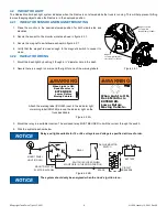
4.2.1 INDICATOR SENSOR AND MAGNET MOUNTING

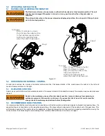
1. Place  the  monitor  in  the  desired  stowed  position  for  both  side-to-side  and

elevation.

2. Secure the sensor to the monitor’s inlet as shown in figure 4.2.1.

3. Secure the magnet to exit elbow as shown in figure 4.2.1.

4. Verify that the magnet is close enough to the magnetic switch to cause it to

close.

4.2.2 INDICATOR WIRING

1. Mount the dash light by pushing it though a ½” diameter hole in the dash.

2. Assure there is enough room around the light for one of the warning labels.

Figure 4.2.2A

3. Mount the relay in a suitable location. The enclosed relay MUST BE USED to limit the current through the switch.

4. Wire the system as show below.

Figure 4.2.2B

NOTICE

Relay and light available for 12 or 24 volt systems. Voltage is specified at time of order. 

NOTICE

The system should only be energized when the truck’s ignition is on. 

Magnet
Secure with Stainless 
Steel Wire Tie (Y3534)

Magnet Switch
Secure with 
Band Clamp (Y3506)

Figure 4.2.1

When Light is ON,

 Deck Monitor is

 Lower Before

Moving Vehicle.

EXTENDED.

XG

L0

2

0

WARNING

XGL025

WARNING

When Light is ON,

Deck Monitor is

EXTENDED.

Lower Before

Moving Vehicle.

Attach the warning label (XGL020) next to the indicator light 

or warning label (XGL025) around the indicator light on the 

truck dashboard.

V4155 Relay 12VDC

15VDC Max

10 Watt Coil Max

RADIUS MONITOR

SWITCH

MOUNT RELAY ON

ELECTRICAL PANEL

BATTERY

SPARE

CIRCUIT

BREAKERS

87

86

85

30

87a

SWITCH IS CLOSED WHEN 

MONITOR IS IN THE DOWN POSITION

MOUNT PANEL

LIGHT IN DASH

RELAY

Содержание RADIUS Series

Страница 1: ...ning is a misuse of this equipment Obtain safety information at tft com serial number This equipment is intended for use by trained and qualified emergency services personnel for firefighting All pers...

Страница 2: ...nt you may be called upon to use 3 It is your responsibility to know that you have been properly trained in Fire ghting and or Emergency Response and in the use precautions and care of any equipment y...

Страница 3: ...GAUGE PORT 4 7 AUTOMATIC DRAIN 5 0 OPERATING INSTRUCTIONS 5 1 RAISING AND LOWERING THE MONITOR 5 2 HORIZONTAL ROTATIONAL CONTROL 5 3 ELEVATION CONTROL 5 4 RECOMMENDED PARK POSITION 6 0 FLOW CHARACTERI...

Страница 4: ...pression See flow graphs WARNING This equipment is intended for use by trained personnel for firefighting Use of this equipment for other purposes may involve hazards not addressed by this manual Seek...

Страница 5: ...150 Figure 3 2A Radius Monitor Operating Envelope 3 Inlet Nozzle A flows 500 gpm 1900 L min at 100 psi 7 9 bar K factor 50 Nozzle B flows 1000 gpm 3800 L min at 100 psi 7 9 bar K factor 100 Nozzle C...

Страница 6: ...MODELS AND TERMS Figure 3 4 3 5 INLET OPTIONS The monitor is equipped with either a 3 or 4 ANSI 150 flange inlet Each of the flange options is equipped with corresponding pipe threads in the inner di...

Страница 7: ...ht Task Force Tips LLC 2021 7 LIY 350 January 13 2021 Rev00 3 6 OVERALL DIMENSIONS Figure 3 0 379 mm 14 92 26 mm 1 01 61 mm 2 41 45 90 381 mm R15 00 291 mm R11 45 90 582 mm 22 89 669 mm 26 32 45 520 m...

Страница 8: ...total of 76 80 ft lb 100 110 N m Figure 4 1 Table 4 1 WARNING Reaction forces generated by master stream flows are capable of causing injury and property damage if not properly supported Monitors sho...

Страница 9: ...g labels Figure 4 2 2A 3 Mount the relay in a suitable location The enclosed relay MUST BE USED to limit the current through the switch 4 Wire the system as show below Figure 4 2 2B NOTICE Relay and l...

Страница 10: ...vel for the Radius monitor is 90 degrees above to 45 degrees below horizontal Refer to Figure 4 4 if limited elevation travel is desired Figure 4 4 Straight Ahead Reference Mark Y4145 Stop Bolt 90 Lef...

Страница 11: ...the screw and washer and reinstall the drain valve assembly CAUTION Mismatched or damaged waterway connections may cause equipment to leak or uncouple under pressure Failure could result in injury Equ...

Страница 12: ...tor is properly parked before moving the truck and know the overall height to avoid damage from overhead obstructions such as doors or bridges WARNING The Radius monitor may be used only in either the...

Страница 13: ...METER 3 5 BAR 4 1 BAR 5 5 BAR 7 BAR FLOW L min REACTION KG FLOW L min REACTION KG FLOW L min REACTION KG FLOW L min REACTION KG 50 mm 3180 140 3480 170 4010 230 4500 290 57 mm 4010 180 4430 220 5110 2...

Страница 14: ...T VERTICAL DISTANCE FEET 2 25 INCH TIP 60 PSI 100 PSI 80 PSI 50 PSI VERTICAL DISTANCE M 0 0 40 0 80 0 20 0 60 0 HORIZONTAL DISTANCE M 0 10 20 0 20 40 60 80 0 0 40 0 80 0 120 0 160 0 200 0 240 0 280 0...

Страница 15: ...a moderate wind can affect stream reach Figure 6 1 1B Effects of Wind on Reach 0 20 40 60 80 100 120 140 160 180 200 0 40 80 120 160 200 240 280 HORIZONTAL DISTANCE FEET 2 25 INCH TIP 100 PSI 1500 GPM...

Страница 16: ...000 500 1190 630 NOZZLE INLET PRESSURE NOZZLE DIAMETER 2 8 BAR 4 1 BAR 5 5 BAR 7 BAR FLOW L min REACTION KG FLOW L min REACTION KG FLOW L min REACTION KG FLOW L min REACTION KG 35 mm 1360 50 1670 80 1...

Страница 17: ...280 0 40 PSI 60 PSI 100 PSI 80 PSI HORIZONTAL DISTANCE FEET VERTICAL DISTANCE FEET VERTICAL DISTANCE M 0 0 4 0 0 80 0 0 0 6 0 0 2 HORIZONTAL DISTANCE M 1 75 INCH TIP 0 10 20 0 20 40 60 80 0 0 40 0 80...

Страница 18: ...moderate wind can affect stream reach Figure 6 2 1B Effects of Wind on Reach 0 40 80 120 160 200 240 280 320 0 20 40 60 80 100 120 140 160 VERTICAL DISTANCE FEET HORIZONTAL DISTANCE FEET 80 0 6 0 4 0...

Страница 19: ...REAM NOZZLES Automatic nozzles maintain a constant pressure by adjusting their orifice to match the available flow Consult the nozzle manufacturer for maximum flow and pressure range In all cases do n...

Страница 20: ...ozzle will increase the stresses on the monitor s gear train and may lead to premature wear Use of a stream straightener with a fog nozzle is not recommended GPM FLOW 920 840 751 1127 1063 1246 1188 9...

Страница 21: ...of its obligations under this limited warranty If TFT makes this election claimant shall return the equipment to TFT free and clear of any liens and encumbrances This is a limited warranty The origin...

Страница 22: ...kote 112 Any scrapes that expose bare aluminum should be cleaned and touched up with enamel paint such as Rust Oleum Replace any missing or damaged parts before returning to service Any equipment take...

Страница 23: ...nce with TFT test procedures Consult factory for the procedure that corresponds to the model and serial number of the equipment Any equipment which fails the related test criteria should be removed fr...

Страница 24: ...BEING PLACED BACK IN SERVICE appliances must be inspected to this checklist 1 All valves if so equipped open and close smoothly and fully 2 The waterway is clear of obstructions 3 There is no damage t...

Отзывы: