


46
9. REMOTE CONTROL
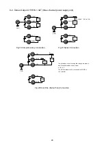
・
Terms used in the descriptions below
Master unit:
A unit that controls the slave units.
Slave units:
All PW-A power supply units controlled by the master unit when the IF-41RS is
used. PW-A power supply units connected with the local bus master unit
through the local bus when the IF-41GU/IF-41USB is used.
Local bus:
A bus for connecting the PW-A power supply units. Use modular cables when the
IF-41RS is used. Use twisted pair cables when the IF-41GU/ IF-41USB is used.
Local bus master:
PW-A power supply units connected directly with the computer when the
IF-41GU/IF-41USB
used.
Note: that the PW-A power supply unit will not accept any other commands than LL1, LC1 and ST0
to 5 when an OHA occurs in it or an alarm is input to it through the external contacts.
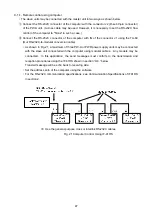
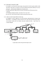
9-1. Connecting IF-41RS
・
It is possible to connect a maximum of four PW-A power supply units (with the IF-41RS units built
in) with a master unit (such as a computer) with modular cables and control the PW-A power
supply units. The PW-A power supply units to be controlled as the slave units must have system
addresses (between 1 and 26).
※
For the address setting procedures, see sections “9-3-2.” and “9-3-3.”.
・
It is recommended that modular cables CB-0603S, 0615S, 0630S or 06100S be used for connection.
・
The maximum cable length of the system is 10 meters between the computer and IF-41RS.
<Precautions>
・
Before connecting the cables, turn off the master unit and slave units.
・
Be sure to connect the IN and OUT terminals of the connectors J1. Connecting the IN (or OUT)
terminals with each other may cause troubles.
Содержание PW16-2ATP
Страница 2: ......
Страница 85: ...75 11 OUTSIDE DIMENSIONS V sec A 18 4 380 4 5 137 1 5 1 5 8 5 124 15 4 138...
Страница 86: ...1850 1 Tsuruma Machida shi Tokyo 194 0004 Japan http www texio jp...