


20
1.3.3 The Rear Panel
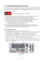
The rear panel of the DL-1060 is shown in
Figure 2-20
. This figure includes
important abbreviated information that should be reviewed before using the
instrument.
Fgure 1-28
1.
VM COMP:
Voltmeter Complete Output Terminal. Outputs a low-true pulse from a
remote interface.
2.
EXT TRIG:
Terminal to be used when choosing external triggering.
3.
USB Connection (USB-TMC):
Connects a remote computer for changing
operation environment instead of the front panel control.
4.
Chassis ground terminal.
5.
Power Module:
Contains the AC line receptacle, power line fuse, and line voltage
setting. It is possible to switch 100Vac, 120Vac, 220Vac, and 240Vac along with
the power-supply voltage selector which is equal to fuse folder.
6.
GPIB (IEEE488.2 Connection)/RS-232:
Connects a remote computer with an IEEE488 cable or RS-232 card for changing
operation environment instead of the front panel control (Model: DL-1060G/VG
,DL-1060R/VR).
1 2 3
4
5
6
Содержание DL-1060
Страница 1: ...INSTRUCTION MANUAL 6 1 2 DIGITAL MULTIMETER DL 1060 DL 1060G DL 1060VG DL 1060R DL 1060VR B71 0180 31...
Страница 91: ...85 3 4 10 Self test Notice Do not use SELF TEST since it is used only for an after sales service operation...
Страница 146: ...7F Towa Fudosan Shin Yokohama Bild 2 18 13 Shin Yokohama Kohoku ku Yokohama Kanagawa 222 0033 Japan http www texio co jp...