a1 [7]
d1 [7]
a2 [7]
d2 [7]
aN [7]
dN [7]
Start
Condition
StopSmpl
Condition
CLK
I/O_ [7]
I/O_[6:0]
a1 [6:0]
a2 [6:0]
d1 [6:0]
d2 [6:0]
aN [6:0] dN [6:0]
50 ns
a0 [7]
d0 [7]
Start
Condition
CLK
I/O_[7]
I/O_[6:0]
a0 [6:0]
d0 [6:0]
xx
d1 [6:0]
d2 [6:0]
d2 [7]
dN [6:0]
d3 [6:0]
dN [7]
xx
StopCont
Continuous Mode
d1 [7]
d3 [7]
50 ns
SLOU186F
–
AUGUST 2006
–
REVISED AUGUST 2010
5.6
Parallel Interface Communication
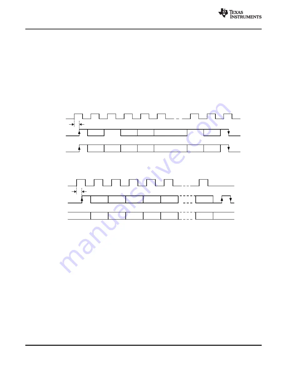
In parallel mode, the start condition is generated on the rising edge of the I/O_7 pin while the CLK is high.
This is used to reset the interface logic.
shows the sequence of the data, with an 8-bit address
word first, followed by data.
Communication is ended by:
•
the StopSmpl condition, where the falling edge on the I/O_7 pin is expected while CLK is high
•
the StopCont condition, where the I/O_7 pin must have a successive rising and falling edge while CLK
is low in order to reset the parallel interface and be ready for the new communication sequence
The StopSmpl condition is also used to terminate the direct mode.
Figure 5-5. Parallel Interface Communication With Simple Stop Condition StopSmpl
Figure 5-6. Parallel Interface Communication With Continuous Stop Condition StopCont
38
System Description
Copyright
©
2006
–
2010, Texas Instruments Incorporated
focus.ti.com:


