4.1
Schematic
www.ti.com
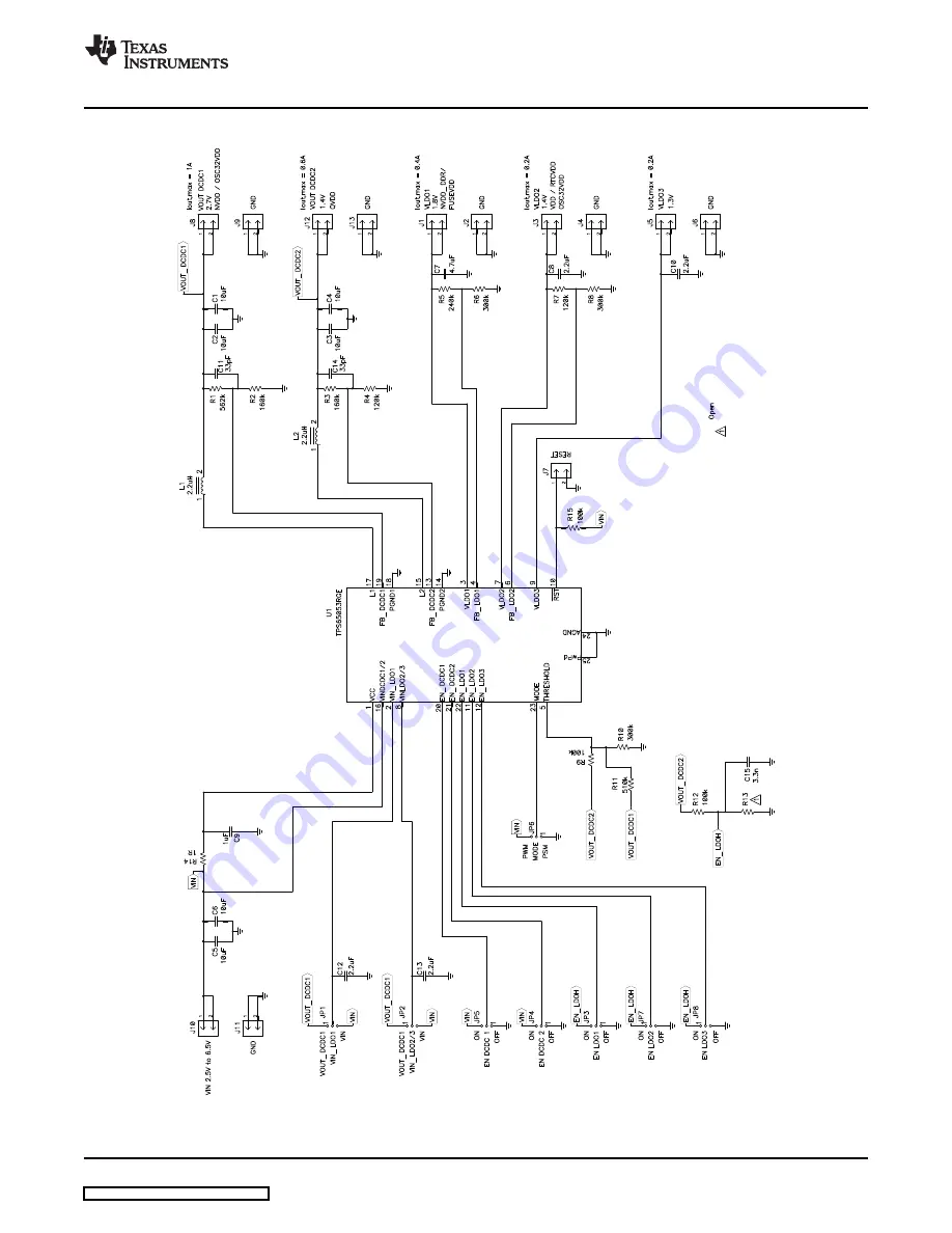
Schematic and Bill of Materials
Figure 5. TPS65053EVM-389 Schematic
SLVU262 – February 2009
TPS65053EVM-389
9
Submit Documentation Feedback
Страница 1: ...10 The Texas Instruments TPS65053EVM 389 evaluation module EVM enables designers to evaluate the operation and performance of the TPS65053 Power Management Integrate Circuit PMIC for applications tha...
Страница 2: ...f supplying up to 200 mA A load can be connected between J5 and J6 GND J6 GND J6 is the return connection of VLDO3 output rail A load can be connected between J6 and J5 VLDO3 J7 RESET This header allo...
Страница 3: ...g LDO1 JP4 EN_DCDC2 Placing a shorting bar between EN_DCDC2 and ON ties the EN pin of DCDC2 to VIN thereby enabling DCDC2 Placing a shorting bar between EN_DCDC2 and OFF ties the EN pin of DCDC2 to GN...
Страница 4: ...53EVM Voltage VDCDC1 2 7 V VDCDC2 1 4 V VLD01 1 8 V VLD02 1 4 V VLD03 1 3 V Table 2 Maximum Load Current Maximum Load TPS65053EVM Current VDCDC1 1 A VDCDC2 600 mA VLD01 400 mA VLD02 200 mA VLD03 200 m...
Страница 5: ...tage to J10 4 Connect all loads to the outputs 5 Turn on input voltage Table 3 Factory EVM Jumper Settings Shunt Location Jumper TPS65053EVM JP1 Between VOUT_DCDC1 and VIN_LDO1 JP2 Between VOUT_DCDC1...
Страница 6: ...yout www ti com This chapter provides the TPS65053EVM 389 board layout and illustrations Figure 2 and Figure 3 show the board layout for the TPS65053EVM 389 PWB Figure 2 Assembly Layer 6 TPS65053EVM 3...
Страница 7: ...www ti com Board Layout Figure 3 Top Layer Routing SLVU262 February 2009 TPS65053EVM 389 7 Submit Documentation Feedback...
Страница 8: ...aterials Schematic and Bill of Materials www ti com Figure 4 Bottom Layer Routing This chapter provides the TPS65053EVM 389 schematic and bill of materials 8 TPS65053EVM 389 SLVU262 February 2009 Subm...
Страница 9: ...4 1 Schematic www ti com Schematic and Bill of Materials Figure 5 TPS65053EVM 389 Schematic SLVU262 February 2009 TPS65053EVM 389 9 Submit Documentation Feedback...
Страница 10: ...ng Any x 2 JP1 JP2 JP3 JP4 0 100 inch 8 Header 3 pin 100mil spacing Any JP5 JP6 JP7 JP8 x 3 0 118 x 2 L1 L2 2 2uH Inductor SMT 1 5A 110milliohm LPS3015 222ML Coilcraft 0 118 inch 1 R1 562k Resistor Ch...
Страница 11: ...or to handling the product This notice contains important safety information about temperatures and voltages For additional information on TI s environmental and or safety programs please contact the...
Страница 12: ...ce TI is not responsible or liable for any such statements TI products are not authorized for use in safety critical applications such as life support where a failure of the TI product would reasonabl...