Board Layout
www.ti.com
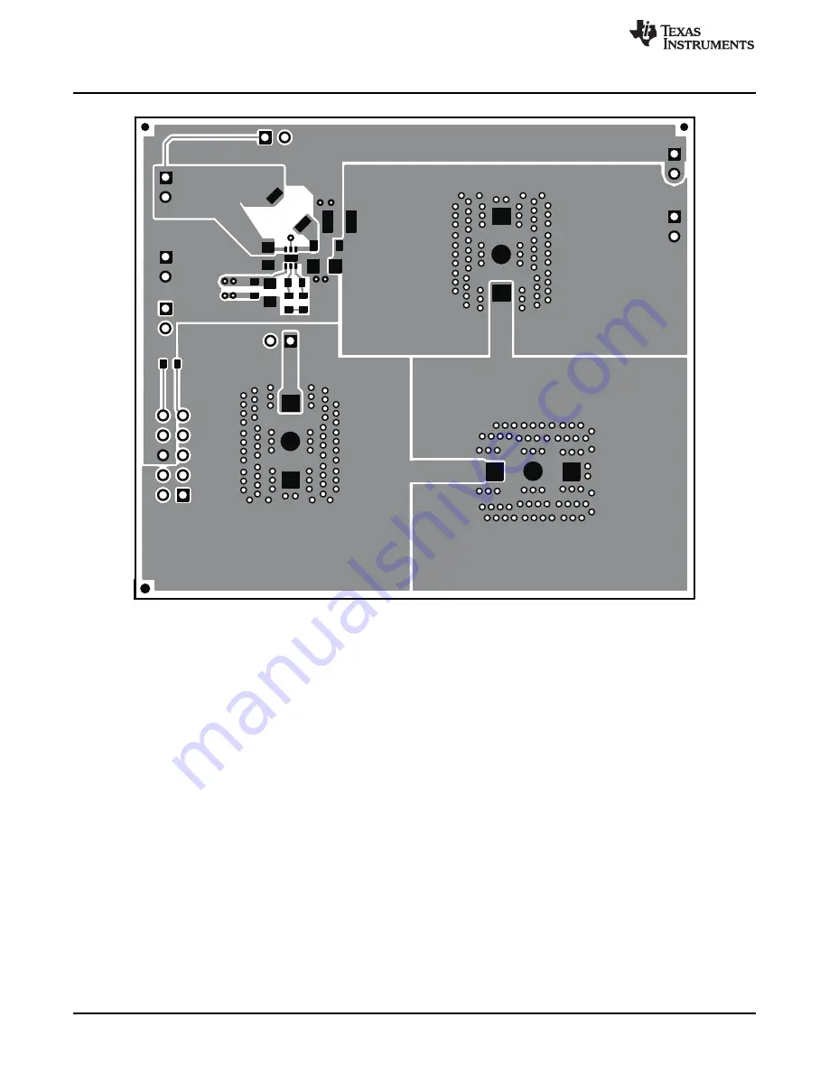
Figure 5. Top-Side Layer
8
TPS61165EVM-283
SLVU224C – January 2008 – Revised February 2010
Submit Documentation Feedback
Copyright © 2008–2010, Texas Instruments Incorporated
Страница 1: ...bill of materials and a schematic diagram Contents 1 Introduction 2 2 Setup and Test Results 2 3 Board Layout 6 4 Schematics and Bill of Materials 9 List of Figures 1 USB Interface Adapter Quick Conn...
Страница 2: ...ion of the EVM the board was designed with devices having 0603 or larger footprints A real world implementation would likely occupy less total board space The inductor and compensation components R1 C...
Страница 3: ...WLEDs from the boost converter feedback path With this jumper removed and jumper JP1 installed the IC s overvoltage protection circuit clamps the boost converter output to 38 V typ WARNING This EVM h...
Страница 4: ...JP1 and connect the appropriately configured function generator to the CTRL side of JP1 The PWM signal s duty cycle is directly proportional to the regulated current In order to implement analog dimmi...
Страница 5: ...e version is installed the software automatically searches on the Internet if connected for updates If a new update is available the software notifies the user of the update downloads and installs the...
Страница 6: ...2 5 Test Results This section provides typical performance characteristics for the TPS61165EVM 283 board Figure 3 LED Efficiency vs Output Current 3 Board Layout This section provides the TPS61165EVM...
Страница 7: ...igh switching frequencies and currents are kept as short as possible to minimize trace inductance Careful attention was given to the routing of high frequency current loops and a single point groundin...
Страница 8: ...Board Layout www ti com Figure 5 Top Side Layer 8 TPS61165EVM 283 SLVU224C January 2008 Revised February 2010 Submit Documentation Feedback Copyright 2008 2010 Texas Instruments Incorporated...
Страница 9: ...limit and therefore not providing the regulated current in the specification table Input voltages greater than the drop across the sum of D2 D4 but less than the 18 V maximum does not damage the IC bu...
Страница 10: ...3M 100mil spacing 4 Wall 2 JP1 JP2 PEC02SAAN Header 2 pin 100mil spacing 0 100 inch 2 PEC02SAAN Sullins 1 L1 10 mH Inductor 67 m 20 0 205 x 0 205 inch A915AY 100M Toko 1 R1 0 Resistor Chip 1 16W 1 06...
Страница 11: ...entation From Texas Instruments TPS61165 High Brightness White LED Driver in 2mm x 2mm QFN Package data sheet SLVS790 11 SLVU224C January 2008 Revised February 2010 TPS61165EVM 283 Submit Documentatio...
Страница 12: ...oduct This notice contains important safety information about temperatures and voltages For additional information on TI s environmental and or safety programs please contact the TI application engine...
Страница 13: ...h statements TI products are not authorized for use in safety critical applications such as life support where a failure of the TI product would reasonably be expected to cause severe personal injury...