Texas Instruments TPS26600-02EVM Скачать руководство пользователя страница 15

www.ti.com

EVM Board Assembly Drawings and Layout Guidelines

15

SLVUAV3A – August 2016 – Revised February 2017

Submit Documentation Feedback

Copyright © 2016–2017, Texas Instruments Incorporated

TPS26600-02EVM: Evaluation Module for TPS2660x

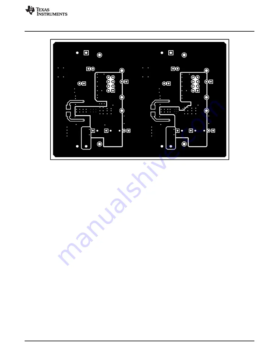
Figure 12. Bottom Layer

Содержание TPS26600-02EVM

Страница 1: ...d in Section 4 4 8 Contents 1 Introduction 2 2 Description 2 3 Schematics 3 4 General Configurations 4 5 EVM Board Assembly Drawings and Layout Guidelines 14 6 Bill Of Materials BOM 16 List of Figures...

Страница 2: ...off Programmable VOUT slew rate control Load current monitor output with 1 5 V A Optional on board transient protection devices like input TVS and output Schottky diodes On board reset switch and fau...

Страница 3: ...3k R16 VIN2 4 2V to 55V IIN2 0 2A 2 23A 47 F C9 887k R14 30 1k R20 1 F C8 0 1 F C7 DNP S2 1 2 3 J11 0 022 F C12 20 0k R18 90 9k R15 402k R19 J8 GND TP14 IMON2 TP16 GND TP11 VIN2 TP12 VOUT2 TP13 SHDNb...

Страница 4: ...ut current monitor TP7 TP8 TP9 GND GND CH2 TP10 FLTb2 CH2 fault indicator TP11 VIN2 CH2 power supply input TP12 VOUT2 CH2 output voltage TP13 SHDNb2 CH2 shutdown input TP14 IMON2 CH2 output current mo...

Страница 5: ...Fault LED CH1 CH2 fault indicators respectively LED turns on when the internal MOSFET is disabled due to any fault condition such as undervoltage overvoltage overload short circuit reverse current an...

Страница 6: ...BK C L 7M 8N 9O DG DG DG DG T 3U 0V W X Y Z T A B U T I L I Z A T I O N H U B M A U N I C 2 B N C 4 M b s Oscilloscope xx xx x xx xx x General Configurations www ti com 6 SLVUAV3A August 2016 Revised...

Страница 7: ...load 6 Connect the negative probe of the DMM to TP7 or TP18 test points the positive probe to the respective test points and verify that the voltages shown in Table 7 are obtained Table 7 TPS26600 02...

Страница 8: ...LEDs D1 D7 turn on whenever the supply voltage reaches either OVP or UVLO limits of the respective channels 9 Disable the power supply and the load 4 4 3 Output Voltage Start Up Time Test Follow the i...

Страница 9: ...VOUT1 TP3 VOUT2 TP12 Channel 2 10V div VIN1 TP2 VIN2 TP11 Channel 4 2 A div Input current into T1 Ve wire Input current into T3 Ve wire Trigger source Channel 2 Trigger level 12 V 1V Trigger polarity...

Страница 10: ...Mode 8 Disable the power supply 9 Set the current limit response mode to latch off by installing the J4 J11 jumper in the position 1 2 10 Set the load resistance to 6 1 and enable the load 11 Enable...

Страница 11: ...start From Latch Off Mode 15 Disable the power supply 16 Set the current limit response mode to circuit breaker with auto retry by uninstalling the J4 J11 jumper 17 Set the load resistance to 6 1 and...

Страница 12: ...est Oscilloscope Setting CH1 Probe Points CH2 Probe Points Channel 1 10 V div VOUT1 TP3 VOUT2 TP12 Channel 2 10 V div VIN1 TP2 VIN2 TP11 Channel 3 20 V div FLTb1 TP1 FLTb2 TP10 Channel 4 2 A div Input...

Страница 13: ...e Single Time base 10 ms div 2 Set the power supply voltage to 24 V and disable the power supply 3 Connect ve terminal of the power supply to either T1 T3 ve terminal connect ve terminal of the power...

Страница 14: ...Documentation Feedback Copyright 2016 2017 Texas Instruments Incorporated TPS26600 02EVM Evaluation Module for TPS2660x 5 EVM Board Assembly Drawings and Layout Guidelines 5 1 PCB Drawings Figure 10...

Страница 15: ...y Drawings and Layout Guidelines 15 SLVUAV3A August 2016 Revised February 2017 Submit Documentation Feedback Copyright 2016 2017 Texas Instruments Incorporated TPS26600 02EVM Evaluation Module for TPS...

Страница 16: ...olutions Header 100mil 4x2 Tin TH Header 4x2 100mil Tin 13 R1 R5 R13 R16 4 24 3k CRCW060324K3FKEA Vishay Dale RES 24 3 k 1 0 1 W 0603 0603 14 R2 R14 2 887k CRCW0603887KFKEA Vishay Dale RES 887 k 1 0 1...

Страница 17: ...Protection PWP0016D 31 C1 C7 0 0 1uF GRM319R72A104KA01D Murata CAP CERM 0 1 F 100 V 10 X7R 1206 1206 32 C4 C11 0 1uF GRM31CR72A105KA01L Murata CAP CERM 1 F 100 V 10 X7R 1206 1206 33 D2 D8 0 51V SMAJ5...

Страница 18: ...ers in the current version Changes from Original August 2016 to A Revision Page Added TPS26601 device to document 1 Changed schematic for board revision B 3 Deleted TP6 and TP15 test points from Test...

Страница 19: ...set forth above or credit User s account for such EVM TI s liability under this warranty shall be limited to EVMs that are returned during the warranty period to the address designated by TI and that...

Страница 20: ...the antenna types listed in the user guide with the maximum permissible gain and required antenna impedance for each antenna type indicated Antenna types not included in this list having a gain great...

Страница 21: ...t the EVM user guide prior to connecting any load to the EVM output If there is uncertainty as to the load specification please contact a TI field representative During normal operation even with the...

Страница 22: ...OST OF REMOVAL OR REINSTALLATION ANCILLARY COSTS TO THE PROCUREMENT OF SUBSTITUTE GOODS OR SERVICES RETESTING OUTSIDE COMPUTER TIME LABOR COSTS LOSS OF GOODWILL LOSS OF PROFITS LOSS OF SAVINGS LOSS OF...

Страница 23: ...TI Resource NO OTHER LICENSE EXPRESS OR IMPLIED BY ESTOPPEL OR OTHERWISE TO ANY OTHER TI INTELLECTUAL PROPERTY RIGHT AND NO LICENSE TO ANY TECHNOLOGY OR INTELLECTUAL PROPERTY RIGHT OF TI OR ANY THIRD...

Страница 24: ...Mouser Electronics Authorized Distributor Click to View Pricing Inventory Delivery Lifecycle Information Texas Instruments TPS26600 02EVM...

Отзывы: