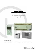
Figure 10-2. Analog/Digital I/O Pads
MUX
MUX
MUX
Pad
Control
Data
Control
GPIO Input
GPIO Output
GPIO Output Enable
Interrupt
Control
Interrupt
GPIODR8R
GPIODR2R
GPIODR4R
GPIOSLR
GPIOPUR
GPIOPDR
GPIOODR
GPIODEN
GPIOAMSEL
GPIOIEV
GPIOIS
GPIOIBE
GPIOIM
GPIORIS
GPIOMIS
GPIOICR
GPIODATA
GPIODIR
Identification Registers
GPIOPeriphID0
GPIOPeriphID1
GPIOPeriphID2
GPIOPeriphID3
GPIOPeriphID4
GPIOPeriphID5
GPIOPeriphID6
GPIOPeriphID7
GPIOPCellID0
GPIOPCellID1
GPIOPCellID2
GPIOPCellID3
Analog Circuitry
(for GPIO pins that
connect to the ADC
input MUX)
ADC
Isolation
Circuit
Pad Output Enable
Package I/O Pin
Pad Input
Pad Output
Analog/Digital
I/O Pad
Commit
Control
GPIOLOCK
GPIOCR
Alternate Input
Alternate Output
Alternate Output Enable
Periph 0
Periph 1
Periph n
Port
Control
GPIOPCTL
DEMUX
GPIODR12R
Mode
Control
GPIOAFSEL
GPIOAMSEL
GPIOADCCTL
GPIODMACTL
GPIOSI
10.3.1
Data Control
The data control registers allow software to configure the operational modes of the GPIOs. The data
direction register configures the GPIO as an input or an output while the data register either captures
incoming data or drives it out to the pads.
Caution – It is possible to create a software sequence that prevents the debugger from connecting to
the TM4C1294NCPDT microcontroller. If the program code loaded into flash immediately changes
the JTAG pins to their GPIO functionality, the debugger may not have enough time to connect and
halt the controller before the JTAG pin functionality switches. As a result, the debugger may be locked
out of the part. This issue can be avoided with a software routine that restores JTAG functionality
based on an external or software trigger. In the case that the software routine is not implemented and
the device is locked out of the part, this issue can be solved by using the TM4C1294NCPDT Flash
Programmer "Unlock" feature. Please refer to
on the TI web for more
information.
June 18, 2014
748
Texas Instruments-Production Data
General-Purpose Input/Outputs (GPIOs)