


then to send the master code byte, software should place the value of the master code byte into
the
I2CMSA
register and write the
I2CMCS
register with 0x50. Either configuration places the I
2
C
master peripheral in High-speed mode, and all subsequent transfers (until STOP) are carried out
at High-speed data rate using the normal
I2CMCS
command bits, without setting the
HS
bit in the
I2CMCS
register. Again, setting the
HS
bit in the
I2CMCS
register is only necessary during the
master code byte.
When operating as a High-speed slave, there is no additional software required.
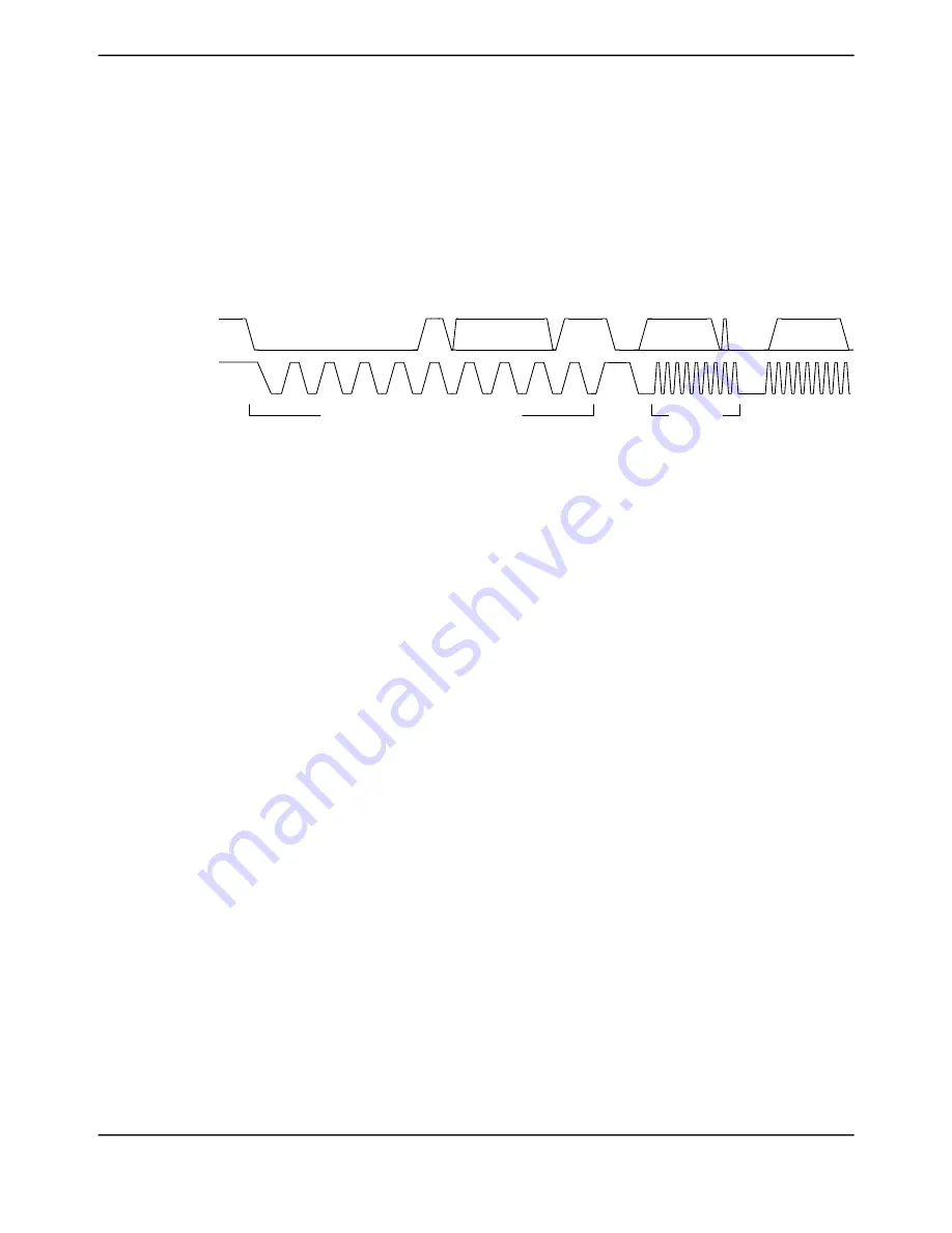
Figure 18-7. High-Speed Data Format
SDA
SCL
Device-Specific
NAK
Address
R/W
Data
Standard (100 KHz) or Fast Mode (400 KHz)
High Speed
(3.3 Mbps)
Note:
High-Speed mode is 3.4 Mbps, provided correct system clock frequency is set and there is
appropriate pull strength on SCL and SDA lines.
18.3.3
Interrupts
The I
2
C can generate interrupts when the following conditions are observed in the Master Module:
■ Master transaction completed (
RIS
bit)
■ Master arbitration lost (
ARBLOSTRIS
bit)
■ Master Address/Data NACK (
NACKRIS
bit)
■ Master bus timeout (
CLKRIS
bit)
■ Next byte request (
RIS
bit)
■ Stop condition on bus detected (
STOPRIS
bit)
■ Start condition on bus detected (
STARTRIS
bit)
■ RX DMA interrupt pending (
DMARXRIS
bit)
■ TX DMA interrupt pending (
DMATXRIS
bit)
■ Trigger value for FIFO has been reached and a TX FIFO request interrupt is pending (
TXRIS
bit)
■ Trigger value for FIFO has been reached and a RX FIFO request interrupt is pending (
RXRIS
bit)
■ Transmit FIFO is empty (
TXFERIS
bit)
■ Receive FIFO is full (
RXFFRIS
bit)
Interrupts are generated when the following conditions are observed in the Slave Module:
June 18, 2014
1286
Texas Instruments-Production Data
Inter-Integrated Circuit (I
2
C) Interface


