background image

User’s Guide

OPT4001YMNEVM User's Guide

ABSTRACT

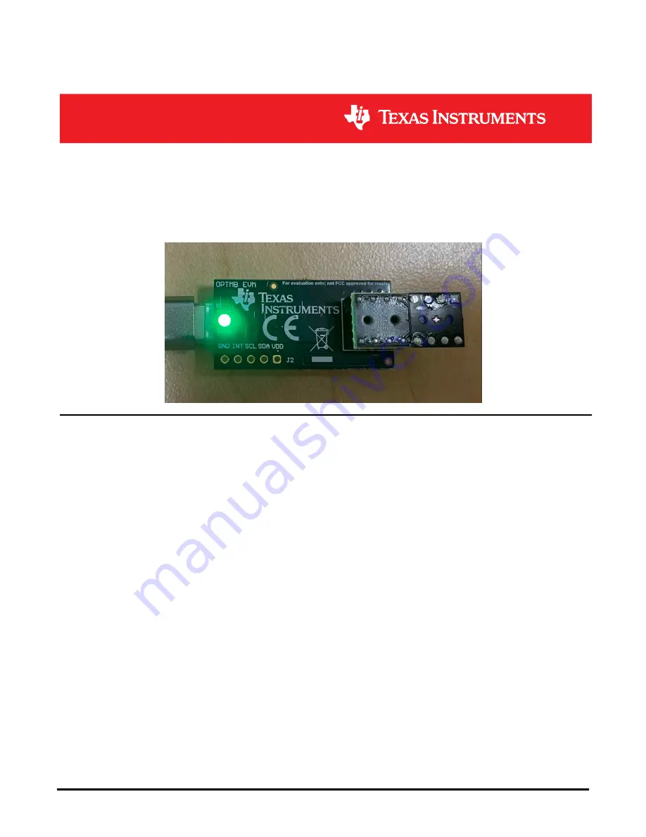
This user’s guide describes the characteristics, operation, and use of the OPT4001YMNEVM evaluation module. 
It discusses how to set up and configure the software and hardware, and reviews various aspects of the program 
operation. Throughout this document, the terms evaluation board, evaluation module, and EVM are synonymous 
with the OPT4001YMNEVM. This document also includes an electrical schematic, printed circuit board (PCB) 
layout drawings, and a parts list for the EVM.

Table of Contents

1 Overview

..................................................................................................................................................................................

3

1.1 OPT4001YMNEVM Kit Contents.......................................................................................................................................

3

1.2 Related Documentation from Texas Instruments...............................................................................................................

4

2 OPT4001YMNEVM Hardware

.................................................................................................................................................

5

2.1 Theory of Operation for the OPT4001YMNEVM................................................................................................................

6

2.2 OPT4001YMNEVM Hardware Overview...........................................................................................................................

6

3 OPT4001YMNEVM Software

..................................................................................................................................................

7

3.1 Hardware Requirements....................................................................................................................................................

7

3.2 Software Installation...........................................................................................................................................................

7

3.3 Typical OPT4001YMNEVM Hardware Setup...................................................................................................................

11

3.4 Launching the OPT4001EVM Software...........................................................................................................................

13

3.5 OPT4001EVM Software Operation..................................................................................................................................

14

4 Schematic, PCB Layout, and Bill of Materials

...................................................................................................................

19

4.1 Flex Coupon Board..........................................................................................................................................................

19

4.2 Rigid Coupon Board.........................................................................................................................................................

21

4.3 Motherboard.....................................................................................................................................................................

24

5 Troubleshooting

....................................................................................................................................................................

28

5.1 Microsoft Windows 7 Manual Driver Installation..............................................................................................................

28

List of Figures

Figure 1-1. Hardware Included with OPT4001YMNEVM Kit.......................................................................................................

3

Figure 2-1. EVM Hardware Setup................................................................................................................................................

5

Figure 3-1. OPT4001YMNEVM Software-Installation File...........................................................................................................

7

Figure 3-2. OPT4001YMNEVM Software-Installation Launch.....................................................................................................

8

Figure 3-3. OPT4001YMNEVM Software-Installation Prompts...................................................................................................

8

Figure 3-4. OPT4001YMNEVM Software-Installation Prompts...................................................................................................

9

Figure 3-5. OPT4001YMNEVM Software-Installation Prompts...................................................................................................

9

www.ti.com

Table of Contents

SBOU278 – DECEMBER 2021

Submit Document Feedback

OPT4001YMNEVM User's Guide

1

Copyright © 2021 Texas Instruments Incorporated

Содержание OPT4001YMNEVM

Страница 1: ...iew 6 3 OPT4001YMNEVM Software 7 3 1 Hardware Requirements 7 3 2 Software Installation 7 3 3 Typical OPT4001YMNEVM Hardware Setup 11 3 4 Launching the OPT4001EVM Software 13 3 5 OPT4001EVM Software Operation 14 4 Schematic PCB Layout and Bill of Materials 19 4 1 Flex Coupon Board 19 4 2 Rigid Coupon Board 21 4 3 Motherboard 24 5 Troubleshooting 28 5 1 Microsoft Windows 7 Manual Driver Installation...

Страница 2: ...op Layer Assembly Drawing 20 Figure 4 6 PCB Bottom Layer Assembly Drawing 20 Figure 4 7 OPT4001 Coupon Rigid Board Schematic 21 Figure 4 8 PCB Top Layer 22 Figure 4 9 PCB Bottom Layer 22 Figure 4 10 PCB Top Layer Assembly Drawing 22 Figure 4 11 PCB Bottom Layer Assembly Drawing 23 Figure 4 12 OPTMBEVM Schematic 24 Figure 4 13 PCB Top Layer 25 Figure 4 14 PCB Bottom Layer 25 Figure 4 15 PCB Top Lay...

Страница 3: ...ll relay USB commands from the EVM GUI software running on the PC to the OPT4001 IC through I2C The second is the OPT4001YMN coupon board which contains the OPT4001YMN and its support circuitry The coupon board consists of a flex PCB soldered to a rigid board This allows the coupon to be easily plugged and unplugged as the rigid board adds strength to the flex board 1 1 OPT4001YMNEVM Kit Contents ...

Страница 4: ...he time of the writing of this document The latest revision can be found by clicking the link Table 1 2 and is also available from the TI web site the Texas Instruments Literature Response Center at 800 477 8924 and the Product Information Center at 972 644 5580 When ordering identify the document by both title and literature number Table 1 2 Related Documentation Document Literature Number OPT400...

Страница 5: ...t and ships with a USB C to USB A cable The OPTMBEVM board acts as a bridge between the software running on the PC and the OPT4001YMN coupon board The MSP430 on the OPTMBEVM receives USB commands from the PC and communicates with the OPT4001YMN over I2C Figure 2 1 EVM Hardware Setup www ti com OPT4001YMNEVM Hardware SBOU278 DECEMBER 2021 Submit Document Feedback OPT4001YMNEVM User s Guide 5 Copyri...

Страница 6: ... 1 Also note the warnings below Specifically that the flex part of the coupon should not be pressed on If unplugging and replugging the coupon into the motherboard the coupon should only be handled by the rigid part and no part of the flex should be pressed on Then connect the USB cable CAUTION This EVM contains a flex PCB on which the OPT4001 IC is mounted Flex PCBs are sensitive and should be ha...

Страница 7: ...n other Windows operating systems 3 2 Software Installation The OPT4001YMNEVM software is available through the OPT4001YMNEVM Product Folder on the TI web site www ti com To install the software to your computer navigate to the OPT4001YMNEVM software and open the installer directory Launch the OPT4001YMNEVM installation file OPT4001YMNEVM_GUI exe as shown in the figure below Figure 3 1 OPT4001YMNE...

Страница 8: ...stallation Launch Follow the prompts as shown in Figure 3 3 to Figure 3 8 to install the OPT4001YMNEVM software Figure 3 3 OPT4001YMNEVM Software Installation Prompts OPT4001YMNEVM Software www ti com 8 OPT4001YMNEVM User s Guide SBOU278 DECEMBER 2021 Submit Document Feedback Copyright 2021 Texas Instruments Incorporated ...

Страница 9: ...e Installation Prompts Figure 3 5 OPT4001YMNEVM Software Installation Prompts www ti com OPT4001YMNEVM Software SBOU278 DECEMBER 2021 Submit Document Feedback OPT4001YMNEVM User s Guide 9 Copyright 2021 Texas Instruments Incorporated ...

Страница 10: ...e Installation Prompts Figure 3 7 OPT4001YMNEVM Software Installation Prompts OPT4001YMNEVM Software www ti com 10 OPT4001YMNEVM User s Guide SBOU278 DECEMBER 2021 Submit Document Feedback Copyright 2021 Texas Instruments Incorporated ...

Страница 11: ... computer The green light will light up on the EVM as shown in Figure 3 9 Figure 3 9 Typical Hardware Connection When the EVM is plugged into the USB port of the computer it will enumerate as two com ports This will show up in the Windows device manager as show in Figure 3 10 www ti com OPT4001YMNEVM Software SBOU278 DECEMBER 2021 Submit Document Feedback OPT4001YMNEVM User s Guide 11 Copyright 20...

Страница 12: ...ndows shows a notification that a driver is not found for the device connected see the instructions to manually install drivers in Section 5 1 before proceeding OPT4001YMNEVM Software www ti com 12 OPT4001YMNEVM User s Guide SBOU278 DECEMBER 2021 Submit Document Feedback Copyright 2021 Texas Instruments Incorporated ...

Страница 13: ...001EVM GUI software is launched this means that the EVM motherboard was not detected Check the USB connection and that the motherboard appears in the device manager as shown in Section 3 3 A green light will appear on the motherboard if it is receiving power from the PC and the GUI start capture button has not been enabled Figure 3 12 Hardware Error Message www ti com OPT4001YMNEVM Software SBOU27...

Страница 14: ... command REGRx01 Failed is displayed this means that the OPT4001 IC or coupon is not detected by the motherboard Ensure the coupon is plugged in and properly oriented 3 5 2 Feature Descriptions Lux Plot In the center of the GUI window you will see a plot showing the lux reading from the device on the y axis and the sample number on the x axis The plot settings can be tweaked by right clicking on t...

Страница 15: ...e stop capture button to copy all the data into the indicated CSV file When capturing data with save enabled the GUI will initially dump the data to temporary npy files After clicking stop capture this data is written over to the CSV file and npy files are removed Mean Std and the Blue Slider There is a blue slider on the lux plot shown on the right side of the plot in the figure Mean and Std colu...

Страница 16: ...evice registers and allows them to be changed directly Launch the registers view by double clicking on the Registers View button under the Device List box on the right side of the screen OPT4001YMNEVM Software www ti com 16 OPT4001YMNEVM User s Guide SBOU278 DECEMBER 2021 Submit Document Feedback Copyright 2021 Texas Instruments Incorporated ...

Страница 17: ...ipts in the background to capture and display data from the EVM These scripts allow for initialization of the device including loading calibration data from the EVM flash memory launching a live view window with measurement plot and readings and additional functionality such as reading from the flash and selecting a specific LED current for the device to use For advanced users or users looking for...

Страница 18: ... window in the lower left corner of the main window 04 launchGUI py A live view GUI window is launched when running the devInit py script This allows data from the OPT4001 to be viewed on a graph in real time The GUI is created in the launchGUI py example script When running devInit py the launchGUI py script is automatically ran However if the GUI window is closed it can be re launched by directl...

Страница 19: ...board The motherboard contains an MSP430 microcontroller and plugs into a PC through the provided USB cable This section contains the schematics layout and bill of materials for these 3 boards Figure 4 1 OPT4001YMNEVM construction 4 1 Flex Coupon Board 4 1 1 Schematic Figure 4 2 shows the schematic of the OPT4001YMN flex coupon board Figure 4 2 OPT4001 Flex Coupon Board Schematic www ti com Schema...

Страница 20: ...ngs of the top and bottom PCB layers respectively Figure 4 3 PCB Top Layer Figure 4 4 PCB Bottom Layer Figure 4 5 PCB Top Layer Assembly Drawing Figure 4 6 PCB Bottom Layer Assembly Drawing Schematic PCB Layout and Bill of Materials www ti com 20 OPT4001YMNEVM User s Guide SBOU278 DECEMBER 2021 Submit Document Feedback Copyright 2021 Texas Instruments Incorporated ...

Страница 21: ...S With Excellent AngularIR Rejection OPT3004DTS Texas Instruments 4 2 Rigid Coupon Board 4 2 1 Schematic Figure 4 7 shows the schematic of the OPT4001YMN coupon rigid board C1 is a bypass capacitor for device VDD Figure 4 7 OPT4001 Coupon Rigid Board Schematic www ti com Schematic PCB Layout and Bill of Materials SBOU278 DECEMBER 2021 Submit Document Feedback OPT4001YMNEVM User s Guide 21 Copyrigh...

Страница 22: ... show the assembly drawings of the top and bottom PCB layers respectively Figure 4 8 PCB Top Layer Figure 4 9 PCB Bottom Layer Figure 4 10 PCB Top Layer Assembly Drawing Schematic PCB Layout and Bill of Materials www ti com 22 OPT4001YMNEVM User s Guide SBOU278 DECEMBER 2021 Submit Document Feedback Copyright 2021 Texas Instruments Incorporated ...

Страница 23: ...ity Description Part Number Manufacturer C1 1 CAP CERM 1 uF 10 V 10 X7S AEC Q200 Grade 1 0402 GCM155C71A105KE38D MuRata J1 J2 J3 J4 J5 J6 J7 J8 8 PC Pin Terminal Connector Through Hole Gold 0 017 0 43mm Dia 3121 2 00 15 00 00 08 0 Mill Max www ti com Schematic PCB Layout and Bill of Materials SBOU278 DECEMBER 2021 Submit Document Feedback OPT4001YMNEVM User s Guide 23 Copyright 2021 Texas Instrume...

Страница 24: ... containing the OPT4001 plugs into the motherboard through the socket The OPTMBEVM board provides easy access to the I2C INT VDD and GND lines The header J2 is depopulated on the EVM by default and its labeled through hole pads can be used to access the lines Alternatively a header can be populated at J2 for easier access Figure 4 12 OPTMBEVM Schematic Schematic PCB Layout and Bill of Materials ww...

Страница 25: ...5 and Figure 4 16 show the assembly drawings of the top and bottom PCB layers respectively Figure 4 13 PCB Top Layer Figure 4 14 PCB Bottom Layer www ti com Schematic PCB Layout and Bill of Materials SBOU278 DECEMBER 2021 Submit Document Feedback OPT4001YMNEVM User s Guide 25 Copyright 2021 Texas Instruments Incorporated ...

Страница 26: ...ly Drawing Figure 4 16 PCB Bottom Layer Assembly Drawing Schematic PCB Layout and Bill of Materials www ti com 26 OPT4001YMNEVM User s Guide SBOU278 DECEMBER 2021 Submit Document Feedback Copyright 2021 Texas Instruments Incorporated ...

Страница 27: ...MD 5 1K OHM 5 1 20W 0201 CRCW02015K10JNED Vishay Dale S1 1 Switch Tactile SPST NO 0 05A 12V SMD RS 032G05A3 SM RT C K Components U1 1 Socket DIP 8 2 54 mm Pitch SMT 114 87 308 41 134161 Preci Dip U2 1 Low Capacitance 15 kV ESD Protection Array for High Speed Data Interfaces 2 Channels 40 to 85 degC 6 pin SON DRS Green RoHS no Sb Br TPD2E001DRST NM Texas Instruments U3 1 Single Output Low Noise LDO...

Страница 28: ... please use the following steps to correctly install the USB drivers If two USB Serial Device devices show up as COM ports automatically as is the case with Windows 10 then this section can be skipped Figure 5 1 OPT4001YMNEVM on Microsoft Windows 7 With Drivers not Installed 1 Open the device manager 2 Right click on USB Serial Device and select Properties Troubleshooting www ti com 28 OPT4001YMNE...

Страница 29: ...date Driver button 4 Click Browse my computer for driver software www ti com Troubleshooting SBOU278 DECEMBER 2021 Submit Document Feedback OPT4001YMNEVM User s Guide 29 Copyright 2021 Texas Instruments Incorporated ...

Страница 30: ...of device drivers on my computer 6 Select Show All Devices and click the Next button Troubleshooting www ti com 30 OPT4001YMNEVM User s Guide SBOU278 DECEMBER 2021 Submit Document Feedback Copyright 2021 Texas Instruments Incorporated ...

Страница 31: ... C Users username Documents Texas Instruments Latte projects OPT4001 drivers and choose MSP430_CDC Click the Open button www ti com Troubleshooting SBOU278 DECEMBER 2021 Submit Document Feedback OPT4001YMNEVM User s Guide 31 Copyright 2021 Texas Instruments Incorporated ...

Страница 32: ...ect the first USB serial device and click the Next button 12 Click the Yes button Troubleshooting www ti com 32 OPT4001YMNEVM User s Guide SBOU278 DECEMBER 2021 Submit Document Feedback Copyright 2021 Texas Instruments Incorporated ...

Страница 33: ...p 2 and step 11 In step 2 make sure to right click the second USB Serial Device Likewise on step 11 make sure to select the second USB Serial Device when installing the driver as the following figure shows www ti com Troubleshooting SBOU278 DECEMBER 2021 Submit Document Feedback OPT4001YMNEVM User s Guide 33 Copyright 2021 Texas Instruments Incorporated ...

Страница 34: ...The two USB Serial Device devices should now appear in the device manager under Ports COM LPT as the following image shows Troubleshooting www ti com 34 OPT4001YMNEVM User s Guide SBOU278 DECEMBER 2021 Submit Document Feedback Copyright 2021 Texas Instruments Incorporated ...

Страница 35: ...other than TI b the nonconformity resulted from User s design specifications or instructions for such EVMs or improper system design or c User has not paid on time Testing and other quality control techniques are used to the extent TI deems necessary TI does not test all parameters of each EVM User s claims against TI under this Section 2 are void if User fails to notify TI of any apparent defects...

Страница 36: ... These limits are designed to provide reasonable protection against harmful interference in a residential installation This equipment generates uses and can radiate radio frequency energy and if not installed and used in accordance with the instructions may cause harmful interference to radio communications However there is no guarantee that interference will not occur in a particular installation...

Страница 37: ...y for convenience and should be verified by User 1 Use EVMs in a shielded room or any other test facility as defined in the notification 173 issued by Ministry of Internal Affairs and Communications on March 28 2006 based on Sub section 1 1 of Article 6 of the Ministry s Rule for Enforcement of Radio Law of Japan 2 Use EVMs only after User obtains the license of Test Radio Station as provided in R...

Страница 38: ... any interfaces electronic and or mechanical between the EVM and any human body are designed with suitable isolation and means to safely limit accessible leakage currents to minimize the risk of electrical shock hazard User assumes all responsibility and liability for any improper or unsafe handling or use of the EVM by User or its employees affiliates contractors or designees 4 4 User assumes all...

Страница 39: ...OR DAMAGES ARE CLAIMED THE EXISTENCE OF MORE THAN ONE CLAIM SHALL NOT ENLARGE OR EXTEND THIS LIMIT 9 Return Policy Except as otherwise provided TI does not offer any refunds returns or exchanges Furthermore no return of EVM s will be accepted if the package has been opened and no return of the EVM s will be accepted if they are damaged or otherwise not in a resalable condition If User feels it has...

Страница 40: ...o change without notice TI grants you permission to use these resources only for development of an application that uses the TI products described in the resource Other reproduction and display of these resources is prohibited No license is granted to any other TI intellectual property right or to any third party intellectual property right TI disclaims responsibility for and you will fully indemn...

Отзывы: