


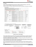

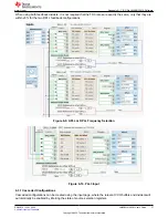


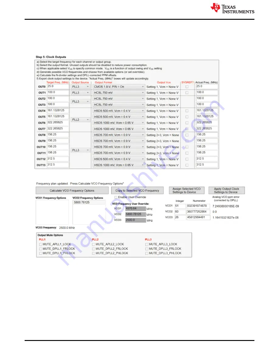
6.1.5 Step 5
Enter the desired target frequencies for each output, as well as the desired output format, output source,
whether the output is SYSREF, and whether the output is being used or not.
Press the
Calculate VCO Frequency Options
button to generate a list of possible VCO frequency combinations.
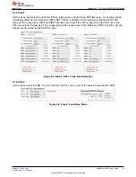
Figure 6-5. Step 5: Clock Outputs
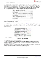
Select a desired combination of VCO frequencies from the list of calculated values. If a specific VCO frequency
is not in this list, a manual override can occur by selecting the
Enable User Override
checkbox and typing in
the desired VCO frequencies. The
Copy to Selected VCO Frequency
box can also be used to copy the VCO
frequency in the list selections to the VCO overrides.
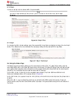
Press the
Assign Selected VCO Settings to Device
button to update the VCO frequencies, then press the
Apply
Output Clock Settings to Device
button. By default, the analog PLL frequencies are shown. The DPLL calculated
frequency from step 6, however, will result in exact output frequencies.
After the output frequency plan is calculated, ensure that a valid XO input is fed into the device so the APLLs
can lock and generate the required frequencies. The device will not output any clocks until all enabled APLLs are
locked.
Appendix A - TICS Pro LMK5B33414 Software
34
LMK5B33414EVM User's Guide
SNAU279 – JULY 2022
Copyright © 2022 Texas Instruments Incorporated