


After the output frequency plan is calculated, ensure that a valid XO input is fed into the device so the APLLs
can lock and generate the required frequencies. The device will not output any clocks until all enabled APLLs are
locked.
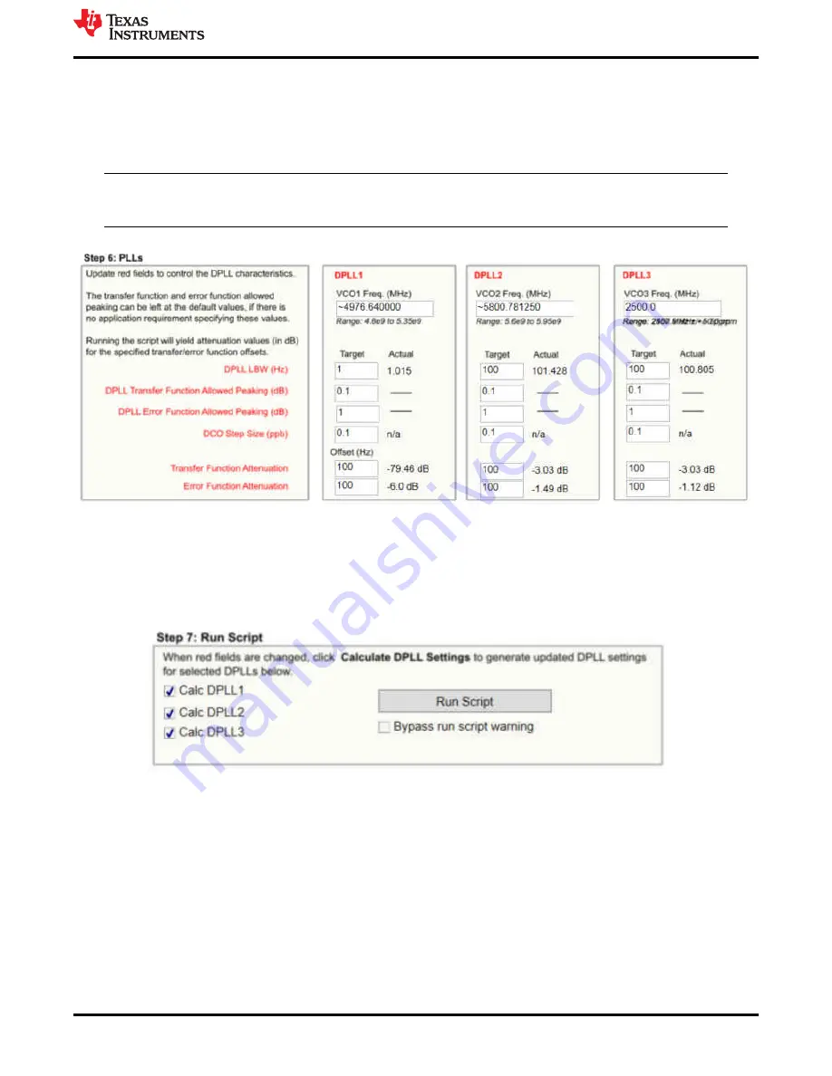
6.1.6 Step 6
For step 6, simply enter the desired DPLL loop bandwidth.
Note
Any time an approximate symbol is shown, a tool tip will allow exact output frequency to be seen by
mousing over the control.
Figure 6-6. Step 6: PLLs
6.1.7 Step 7
To calculate the DPLL divider settings, select which DPLL loop filters and dividers to calculate and press the
Run
Script
button. The software will now run and calculate the necessary settings.
Figure 6-7. Step 7: Run Script
6.2 Using the Status Page
The Status page shows fields pertaining to the current status of the device. To update these fields, click the
Read Status Bits
button or the
Read RO Regs
button in the toolbar. The
Read RO Regs
button will read all read
only registers which provides more information on other pages including the status fields but can take longer to
read back. The read status bits just reads the status bits for this page.
For the DPLL to lock, a reference must be validated and selected in the
Active Reference/Holdover
and
Reference Validated
portions of the window shown in
As the DPLL locks, it is expected to see the LOPL_DPLLx as the last bit to become clear when the phase lock is
acquired.
Appendix A - TICS Pro LMK5B33216 Software
SNAU263A – FEBRUARY 2022 – REVISED JULY 2022
LMK5B33216EVM User's Guide
35
Copyright © 2022 Texas Instruments Incorporated