Schematic
www.ti.com
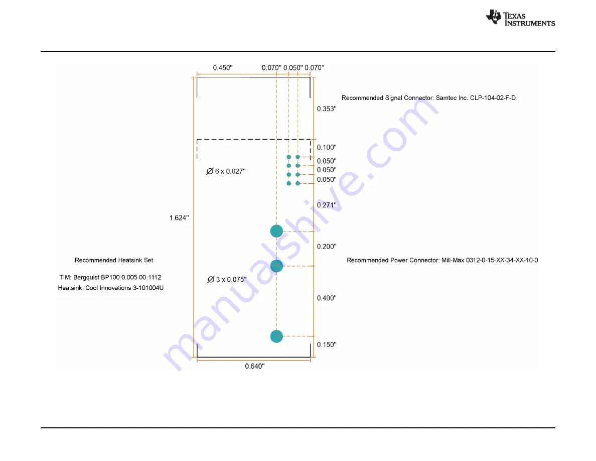
10
SNOU166 – February 2019
Submit Documentation Feedback
Copyright © 2019, Texas Instruments Incorporated
LMG3411R150-031 EVM user guide
Figure 7. Recommended Footprint for LMG3411EVM-031
Страница 1: ... 18 8 Bill of Materials 21 List of Figures 1 Simplified LMG3411EVM 031 Schematic 5 2 Top Side View of LMG3411EVM 031 6 3 Back Side View of LMG3411EVM 031 6 4 Top Side View of LMG3411EVM 031 in Isolated Power Supply Configuration 7 5 Back Side View of LMG3411EVM 031 in Isolated Power Supply Configuration 7 6 LMG3411EVM 031 Schematic 9 7 Recommended Footprint for LMG3411EVM 031 10 8 LMG34XX BB EVM S...
Страница 2: ...11R150 031 EVM user guide List of Tables 1 Logic Pin Function Description 5 2 Power Pin Function Description 5 3 Test Point Functional Description 14 4 List of Terminals 14 5 LMG3411EVM 031 List of Materials 21 6 LMG34XX BB EVM List of Materials 22 Trademarks All trademarks are the property of their respective owners ...
Страница 3: ...rriers and signage must be present in the area where the TI HV EVM and its interface electronics are energized indicating operation of accessible high voltages may be present for the purpose of protecting inadvertent access All interface circuits power supplies evaluation modules instruments meters scopes and other related apparatus used in a development environment exceeding 50 VRMS 75 VDC must b...
Страница 4: ...nd is designed to operate from an AC power supply or a high voltage DC supply Please read this user guide and the safety related documents that come with the EVM package before operating this EVM CAUTION Do not leave the EVM powered when unattended WARNING Hot surface Contact may cause burns Do not touch WARNING High Voltage Electric shock is possible when connecting board to live wire Board must ...
Страница 5: ...Description AGND Logic and bias power ground return pin Functionally isolated from PGND 12V Auxiliary power input for Q2 Used as auxiliary power input for Q1 when the LMG3411EVM 031 is configured in bootstrap mode 5V Auxiliary power input for the LMG3411EVM 031 Used to power logic isolators Used as input bias power of LMG3410R050 devices when configured in isolated power mode FA_2 FAULT signal fro...
Страница 6: ...itance from VSW to VDC PGND and any logic pins The two grounds PGND and AGND are connected to each other on the LMG3411EVM 031 2 1 3 Bootstrap Mode The LMG3411EVM 031 operates in bootstrap mode where the 12V bias voltage is used to power both LMG3411R150 devices The isolated power supply board can be separated from the main board along the score line to save the space The isolated power supply boa...
Страница 7: ...opyright 2019 Texas Instruments Incorporated LMG3411R150 031 EVM user guide Figure 2 Top Side View of LMG3411EVM 031 Figure 3 Back Side View of LMG3411EVM 031 Figure 4 Top Side View of LMG3411EVM 031 in Isolated Power Supply Configuration Figure 5 Back Side View of LMG3411EVM 031 in Isolated Power Supply Configuration ...
Страница 8: ... a fault signal from the LMG3411EVM 031 When the FAULT Protect jumper is placed in the EN mode PWM is disabled when either LMG3410R050 has an active fault This disable is not latching so when the fault clears PWM immediately resumes If FAULT Protect mode is not desired it can be disabled by placing the jumper in the DIS position The FAULT LED will still illuminate when either LMG3411R150 has an ac...
Страница 9: ...board 1 2 J4 Pin to J1 5V AGND 1 2 J5 Pin for J3 ISO_RET_H ISO_12V_H AGND 12V Bot_FET Top_FET Top_FET 5V AGND AGND 10µH L1 10µH L2 4 7uF C4 FAULT_H FAULT_L 0 047uF C12 0 047uF C13 40 2k 50V ns 0 1uF C5 0 1uF C16 1 2 3 4 5 6 7 8 J1 0 R5 0 R7 ISO_RET_H ISO_RET_H ISO_RET_L ISO_RET_L ISO_RET_L DRAIN 1 DRAIN 2 DRAIN 3 DRAIN 4 DRAIN 5 DRAIN 6 DRAIN 7 DRAIN 8 DRAIN 9 DRAIN 10 DRAIN 11 SOURCE 12 SOURCE 13...
Страница 10: ...Schematic www ti com 10 SNOU166 February 2019 Submit Documentation Feedback Copyright 2019 Texas Instruments Incorporated LMG3411R150 031 EVM user guide Figure 7 Recommended Footprint for LMG3411EVM 031 ...
Страница 11: ...630V C17 0 1µF 630V C16 1µF C18 AGND 1µF C20 LOW_2 HIGH_2 HIGH_2 LOW_2 5 4 1 2 3 6 J4 TSW 106 07 G S 1µF C8 VAUX ACMGND 1 2 3 4 5 6 J2 0448120024 AGND1 AGND4 5V AGND 3 4 5 2 U1B SN74LVC2G14DCKR AGND3 0 R23 0 R21 IN 1 OUT 3 GND 2 TAB 4 U4 LM2940IMP 5 0 NOPB 33µF C19 10µF C21 12V 12V 12V Green 1 2 D4 Red 1 2 D3 1 6k R6 1 6k R8 30k R10 30k R16 30k R11 30k R17 30k R18 30k R12 30k R13 30k R19 30k R20 3...
Страница 12: ...recommended to operate the LMG3410EVM 018 and LMG34XX BB EVM with a switching frequency between 50 kHz to 200 kHz Oscilloscope Capable of at least 200 MHz operation A 1 GHz or greater oscilloscope and probes with short ground springs are recommended for accurate measurements DC Multimeter s Capable of 600 V measurement suitable for determining operation and efficiency if desired DC Load Capable of...
Страница 13: ...tes A Probe points for gate drive logic B 100 mil header for PWM input PWM signals to LMG3410EVM 018 and FAULT output C BNC connector for PWM input D 12V bias supply input E FAULT Protection option header F Power stage high voltage input G Probe point for power stage switch node H Power stage high voltage output WARNING To minimize the risk of the electrical shock and burn hazard precautions must ...
Страница 14: ...und for 12 V bias input before filter 5V 5 V bias AGND1 Analog ground for logic PWM Single input PWM signal LDEAD1 Low side PWM signal before dead time generation AGND3 Analog ground for logic HDEAD1 High side PWM signal before dead time generation AGND4 Analog ground for logic LOW Low side PWM signal with dead time HIGH High side PWM signal with dead time AGND2 Analog ground for logic 12V 12 V bi...
Страница 15: ...xt to the EVM as shown in Figure 13 5 2 Startup and Operating Procedure The following procedure is recommended to enable the LMG34XX BB EVM with the LMG3411EVM 031 1 Power up the 12 V bias supply Ensure the top right green Aux Enable LED is illuminated 2 Enable PWM on the function generator 3 Power up high voltage input supply Ensure the red HV Enable LED is illuminated when the input supply is ab...
Страница 16: ...corporated LMG3411R150 031 EVM user guide 6 Typical Characteristics Figure 11 Recommended Probe Connection for Logic Signals Figure 12 Recommended Probe Connection for High Voltage Switch Node Figure 13 Recommended Configuration for Heatsink and Fan Figure 14 Switching Waveforms with 400V input 100kHz 30 duty cycle 4A output ...
Страница 17: ...mentation Feedback Copyright 2019 Texas Instruments Incorporated LMG3411R150 031 EVM user guide Figure 15 Low to High Transition Waveform with 400V input 100kHz 30 duty cycle 4A output Figure 16 High to Low Transition Waveform with 400V Input 100kHz 30 duty cycle 4A Output ...
Страница 18: ...66 February 2019 Submit Documentation Feedback Copyright 2019 Texas Instruments Incorporated LMG3411R150 031 EVM user guide 7 EVM Assembly Drawing and PCB Layout Figure 17 LMG3411EVM 031 Top Layer and Components Figure 18 LMG3411EVM 031 Inner Copper Layer 1 ...
Страница 19: ...B Layout 19 SNOU166 February 2019 Submit Documentation Feedback Copyright 2019 Texas Instruments Incorporated LMG3411R150 031 EVM user guide Figure 19 LMG3411EVM 031 Inner Copper Layer 2 Figure 20 LMG3411EVM 031 Bottom Layer and Components ...
Страница 20: ...ti com 20 SNOU166 February 2019 Submit Documentation Feedback Copyright 2019 Texas Instruments Incorporated LMG3411R150 031 EVM user guide Figure 21 LMG34XX BB EVM Top Layer and Components Figure 22 LMG34XX BB EVM Bottom Layer and Components ...
Страница 21: ...tor 1 H1 Bergquist double sided thermal tape TI Bond Ply100 0 005 127mm 1 cu 27 0mm by 27 0mm BP100 0 005 00 1112 Burgquist 1 H2 Heat sink 1 00 x1 00 3 101004U Cool Innovations 1 J1 Header 1 27mm 4x2 Gold R A TH 20021112 00008T4LF Amphenol FCI 2 J2 J3 Header 50mil 2x1 Gold TH GRPB021VWVN RC Sullins Connector Solutions 2 L1 L2 Inductor Shielded Metal Composite 10 µH 0 65 A 0 768 ohm SMD VLS201610HB...
Страница 22: ... 1 4 Nylon Philips panhead NY PMS 440 0025 PH B and F Fastener Supply 6 H5 H6 H7 H8 H11 H12 Standoff Hex 0 5 L 4 40 Nylon 1902C Keystone 2 J1 J5 Terminal Block 2x1 5 08mm TH 282841 2 TE Connectivity 1 J2 Receptacle 2 54mm 6x1 Gold TH 448120024 Molex 1 J3 Connector TH BNC 112404 Amphenol Connex 1 J4 Header 100mil 6x1 Gold TH TSW 106 07 G S Samtec 1 J6 Terminal Block 2x1 2 54mm TH 282834 2 TE Connec...
Страница 23: ...se resources are subject to change without notice TI grants you permission to use these resources only for development of an application that uses the TI products described in the resource Other reproduction and display of these resources is prohibited No license is granted to any other TI intellectual property right or to any third party intellectual property right TI disclaims responsibility for...